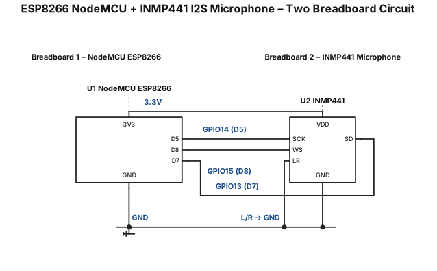
Create a clear, beginner-friendly circuit connection diagram using TWO small breadboards. Components: 1. NodeMCU ESP8266 development board 2. INMP441 digital MEMS microphone 3. Two small solderless breadboards 4. Jumper wires Project: Connect the INMP441 microphone to the NodeMCU ESP8266 using I2S and prepare the circuit for reading audio data in Arduino IDE. Use these exact connections: INMP441 → NodeMCU ESP8266 * VDD → 3.3V * GND → GND * SCK → GPIO14 (D5) * WS → GPIO15 (D8) * SD → GPIO13 (D7) * L/R → GND Breadboard arrangement: * Use the first breadboard mainly for the NodeMCU ESP8266. * Use the second breadboard mainly for the INMP441 microphone. * Connect the power rails between the two breadboards. * Clearly show 3.3V and GND connections. * Do not connect the microphone to 5V. * Show every wire from the correct NodeMCU pin to the correct INMP441 pin. * Label every connection with both the GPIO number and NodeMCU pin name. * Make the diagram physically realistic for a small breadboard. * Keep wires separated and easy to follow. * Include a clear title: "ESP8266 NodeMCU + INMP441 I2S Microphone – Two Breadboard Circuit". * Do not add extra sensors or components. * Make the final diagram suitable for a beginner to reproduce on a real breadboard.
Diagram Examples from Real Visitor Prompts
Browse eligible diagrams shared by FreeDiagram visitors, inspect the exact prompts, and build your own version.
Browse 3298 real creationsAll visitor creations
Showing 1753–1776 of 3298. No stock examples or system defaults. Choose a tool, study a real result, then reopen its prompt as your starting point.
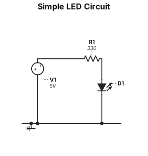
i want to make a simple circuit diagram
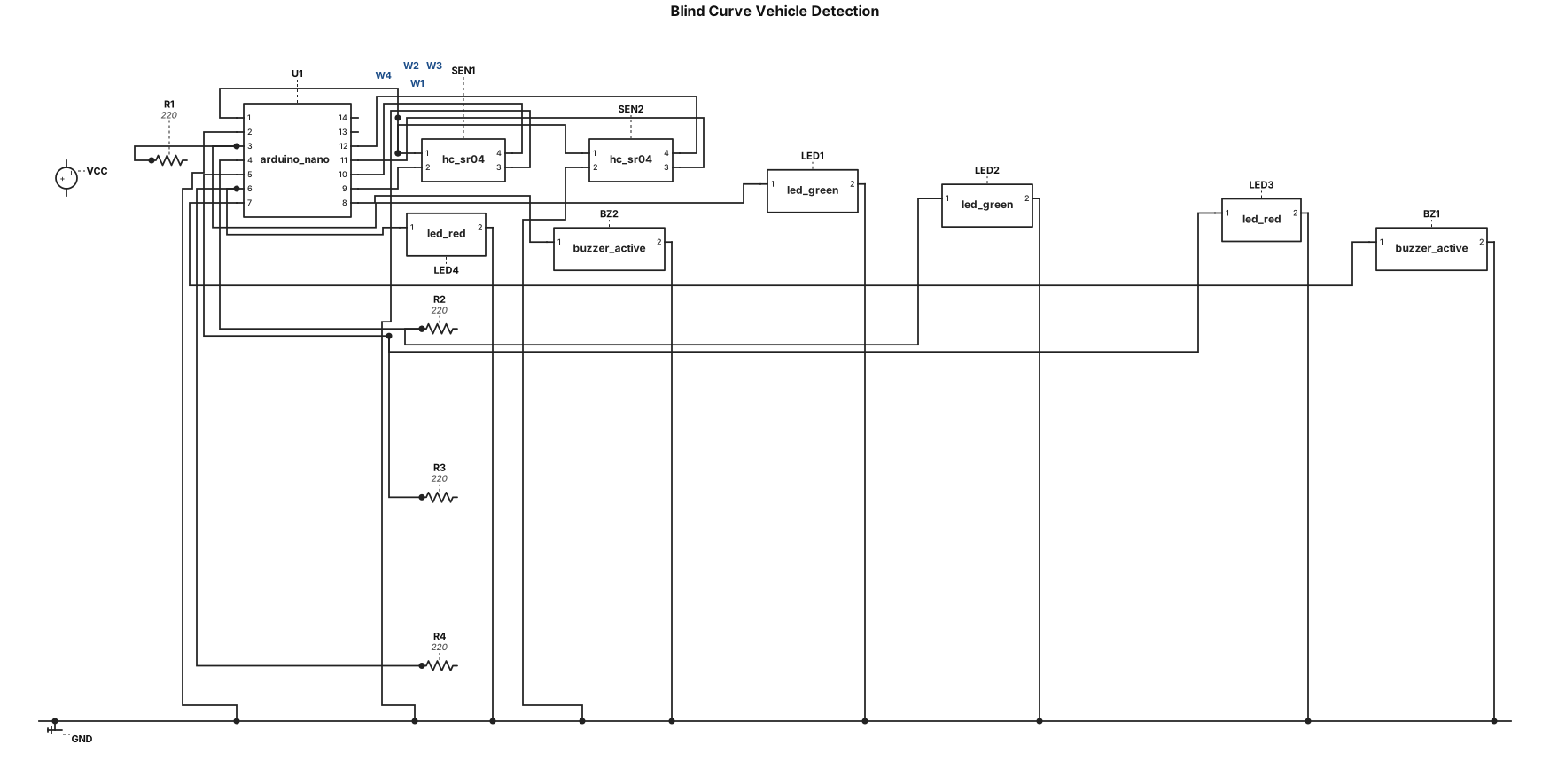
The circuit consists of two HC-SR04 ultrasonic sensors, an Arduino Nano, four LEDs, and two active buzzers. The ultrasonic sensors detect vehicles approaching the blind curve and send distance information to the Arduino Nano. The Arduino processes these inputs and determines whether a vehicle is present on either side. The green LEDs indicate a clear road, while the red LEDs and buzzers provide warnings when a vehicle is detected. If vehicles are detected on both sides simultaneously, both red LEDs and buzzers are activated to indicate a possible collision risk. Input → Processing → Output: HC-SR04 sensors → Arduino Nano → LEDs + Buzzers.
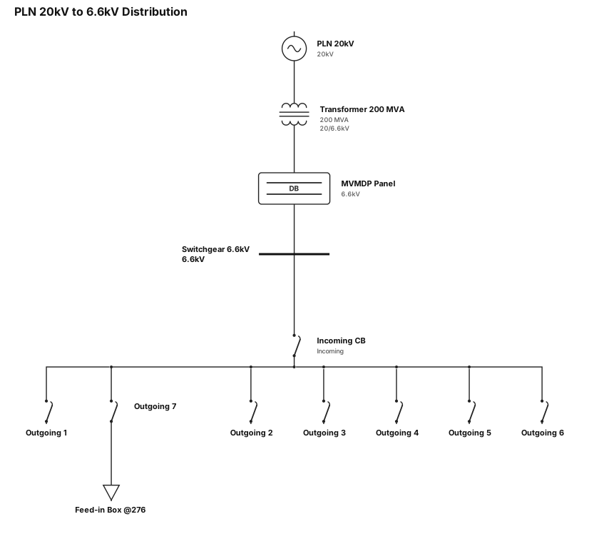
PLN 20KV TO 6,6KV. MVMDP panel (detail) TO SWITCHGEAR 6,6KV to panel feed point . tranformer 200mv. switchgear 1 incoming-7 outgoing to feedin box (@276)
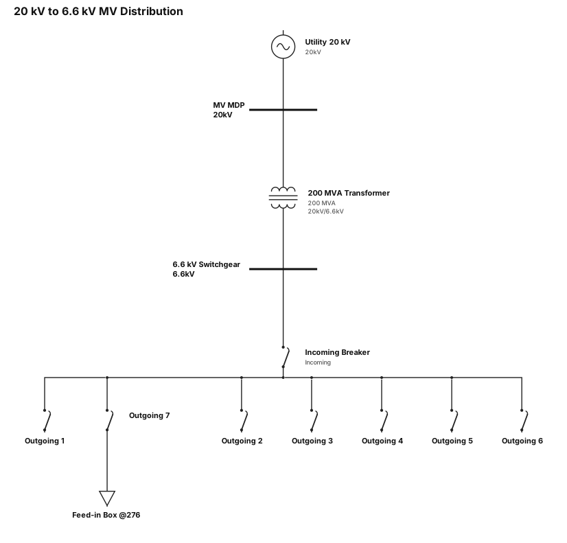
20 KV TO 6,6KV. MVMDP TO SWITCHGEAR 6,6KV. tranformer 200mv. switchgear 1 incoming-7 outgoing to feedin box (@276)
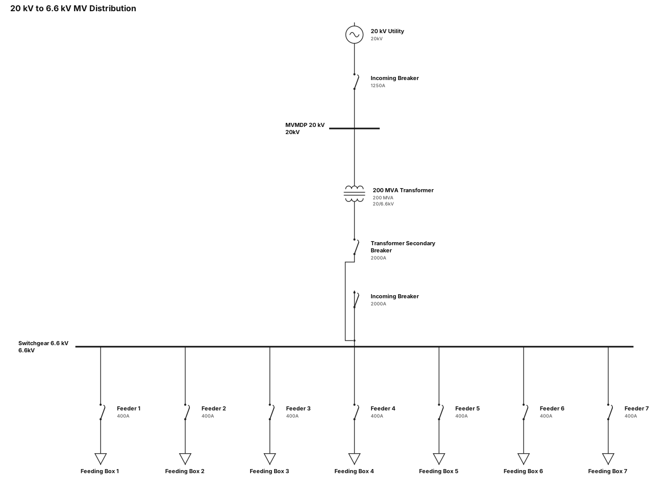
20 KV TO 6,6KV. MVMDP TO SWITCHGEAR 6,6KV. tranformer 200mv. switchgear 1 incoming-7otgoing to feedin box
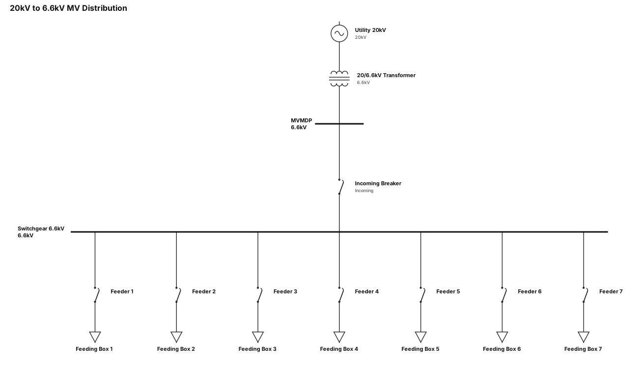
20 KV TO 6,6KV. MVMDP TO SWITCHGEAR 6,6KV. 1incoming-7otgoing to feedin box
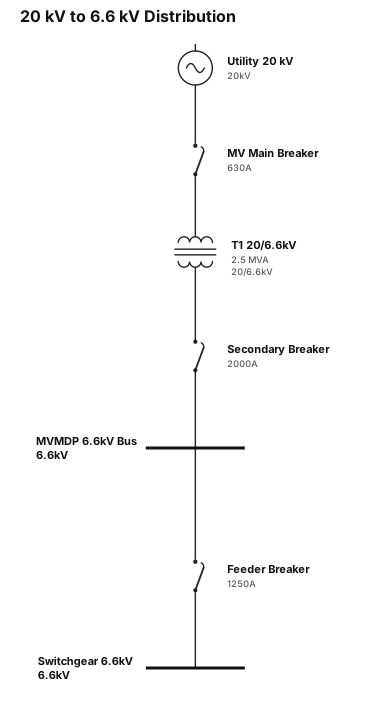
20 KV TO 6,6KV. MVMDP TO SWITCHGEAR 6,6KV
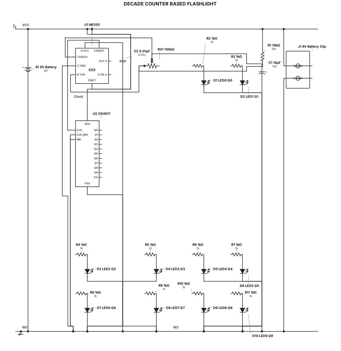
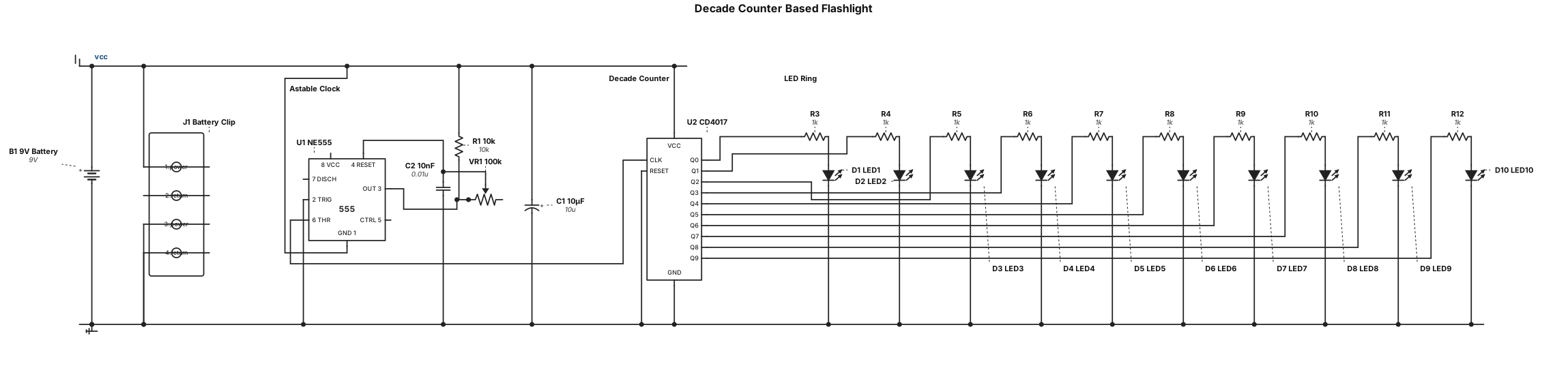
Create a technically accurate, clean electronic schematic titled “DECADE COUNTER BASED FLASHLIGHT”. Use ONLY these components: NE555 timer IC ×1, CD4017 decade counter IC ×1, 10 kΩ resistor ×1, 100 kΩ potentiometer ×1, 1 kΩ resistors ×10, 10 µF 16 V electrolytic capacitor ×1, 0.01 µF (10 nF) capacitor ×1, 5 mm LEDs ×10, 9 V DC battery ×1, 9 V battery clip ×1, solderless breadboard representation ×1, and jumper wires. Show the NE555 in astable mode producing a clock signal. Connect the 555 output to the CD4017 clock input. Show CD4017 outputs Q0, Q1, Q2, Q3, Q4, Q5, Q6, Q7, Q8 and Q9 individually connected to ten LEDs through ten separate 1 kΩ current-limiting resistors. Clearly show VCC and GND connections. Show the 100 kΩ potentiometer and 10 kΩ resistor in the 555 timing network, C1 10 µF as the timing capacitor and C2 0.01 µF as the control-pin capacitor. Clearly label every component, pin connection, Q0–Q9 output, clock connection, VCC, GND, battery positive and negative terminals. Use standard electronic schematic symbols, straight wires, no unnecessary components, white background, professional engineering drawing style.
Create a realistic college electronics project prototype titled “DECADE COUNTER BASED FLASHLIGHT”. Use ONLY these components: 1× NE555 timer IC, 1× CD4017 decade counter IC, 1× 10 kΩ resistor, 1× 100 kΩ potentiometer (VR1), 10× 1 kΩ resistors, 1× 10 µF 16 V electrolytic capacitor (C1), 1× 0.01 µF (10 nF) capacitor (C2), 10× 5 mm LEDs, 1× 9 V DC battery, 1× 9 V battery clip, 1× standard solderless breadboard, and male-to-male jumper wires. Do not add Arduino, ESP32, transistors, relays, switches, sensors, voltage regulators, extra ICs, or any other components. Show the NE555 configured as an astable oscillator generating clock pulses for the CD4017. Connect the CD4017 decade counter outputs Q0–Q9 to the ten LEDs, with one 1 kΩ resistor for each LED. Arrange the ten LEDs in an attractive circular flashlight pattern. Show the 9 V battery connected through the battery clip to the breadboard power rails. Make the prototype physically realistic, neatly wired, educational, suitable for an ECE college project exhibition, clear front three-quarter view, all components clearly visible and labeled, clean laboratory background, realistic breadboard wiring, no fictional components.
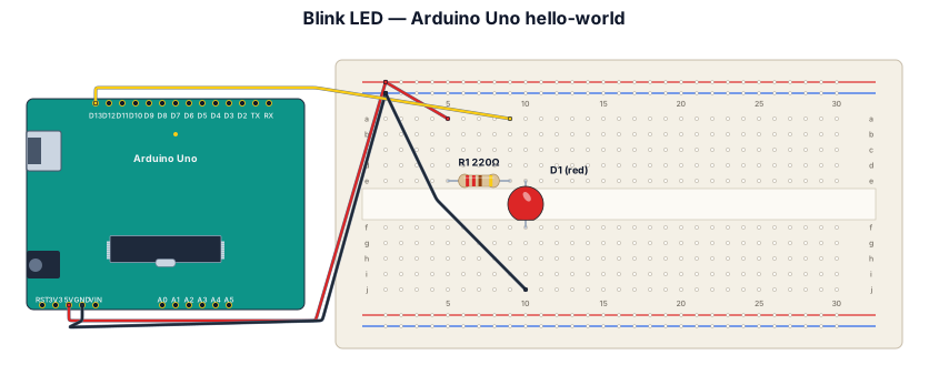
Blink LED hello-world on Arduino Uno with 220-ohm resistor
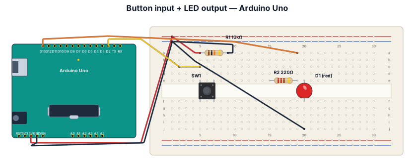
A breadboard wiring diagram for an Arduino Uno reading a button press and lighting an LED: button with pull-down resistor on D2, LED with 220-ohm resistor on D13
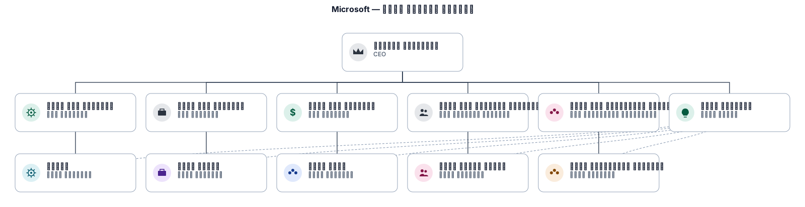
صمّم لي هيكلًا تنظيميًا مصفوفيًا مبسطًا لشركة Microsoft. استخدم الأقسام الآتية: قسم البرمجة، قسم التسويق، قسم المالية، قسم الموارد البشرية، وقسم تكنولوجيا المعلومات. أضف مدير مشروع جديد في المنتصف، واجعل فريق المشروع يتكون من: مبرمج، موظف تسويق، محلل مالي، موظف موارد بشرية، وموظف تكنولوجيا معلومات. أظهر في المخطط أن كل موظف مرتبط بقسمه الأصلي، وفي الوقت نفسه يعمل تحت إشراف مدير المشروع. اجعل خطوط الارتباط واضحة لتوضيح طبيعة الهيكل المصفوفي.

صمّم لي هيكلًا تنظيميًا هرميًا مبسطًا لشركة McDonald’s. اجعل المدير العام في أعلى الهيكل، وتحته: مدير العمليات، مدير التسويق، مدير الموارد البشرية، مدير المالية، ومدير المبيعات. تحت مدير العمليات ضع: مشرف فرع، مشرف مطبخ، وموظفي تجهيز الطلبات. تحت مدير التسويق ضع: موظف تسويق رقمي وموظف إعلانات. تحت مدير الموارد البشرية ضع: موظف توظيف وموظف تدريب. تحت مدير المالية ضع: محاسب وموظف رواتب. تحت مدير المبيعات ضع: مشرف مبيعات وموظفي خدمة الزبائن. رتّب الجميع داخل مخطط تنظيمي واضح من الأعلى إلى الأسفل.
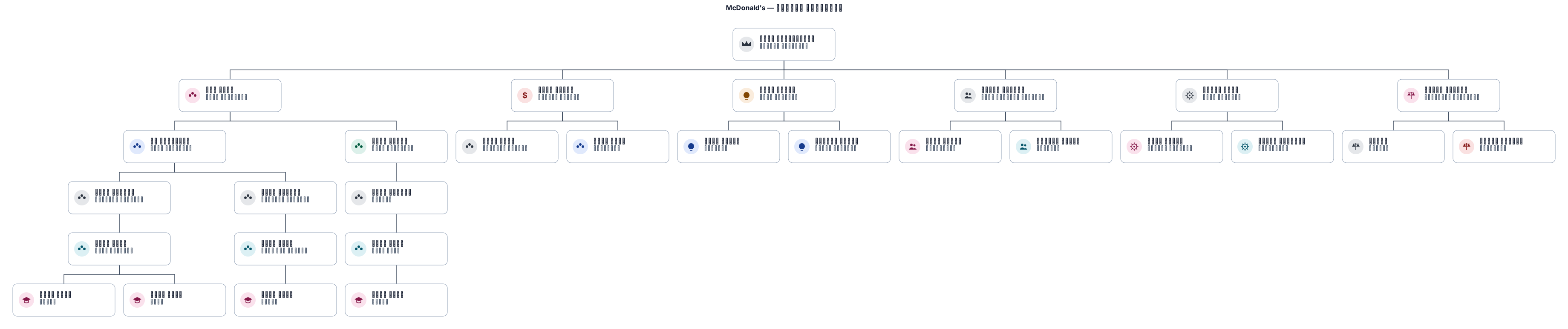
صمّم لي هيكلًا تنظيميًا مناسبًا لشركة McDonald’s، مع ذكر المسميات الوظيفية للمدراء والموظفين، وترتيبهم داخل الهيكل التنظيمي بشكل واضح.
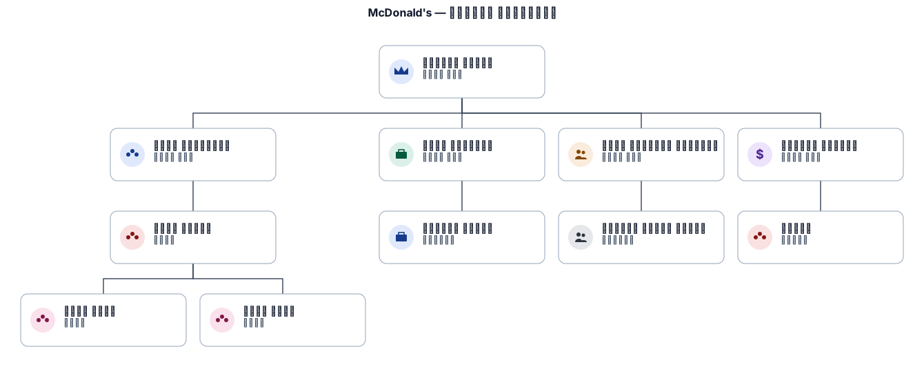
"صمّم هيكلًا تنظيميًا هرميًا مبسطًا لشركة McDonald's، يبدأ بمدير عام ثم مديري الأقسام مثل العمليات، التسويق، الموارد البشرية، والمالية، وتحت كل قسم موظفون تابعون له. اجعل التسلسل الإداري واضحًا."

An org chart for a 30-person startup with a CEO, CTO, CMO, and VP of S"صمّم لي هيكلًا تنظيميًا هرميًا واضحًا لشركة صغيرة. اجعل المدير العام في أعلى الهيكل، وتحته مدير التسويق، مدير الموارد البشرية، مدير المبيعات، ومدير المالية. وتحت كل مدير موظفون تابعون له. أظهر خطوط السلطة والمسؤولية بشكل واضح."ales at the top — then engineering, product, marketing, and sales teams below with their leads

න්යායාත්මක රාමුව (Theoritical framework) සමාජ-ප්රජානන න්යාය ↓ පුද්ගලික සාධක හැසිරීම් + පරිසරය ↓ ස්වයං නියාමිත ඉගෙනුම් න්යාය ↓ සැලසුම් කිරීම ↓ නිරීක්ෂණය ↓ ස්වයං ඇගයීම ↓ ස්වයං නියාමිත ඉගෙනුම් උපායමාර්ග ↓ ZPD න්යාය ↓ මඟපෙන්වීම හා Scaffolding ↓ ගණිත හා භෞතික විද්යා ඉගෙනුම් අභියෝග ජයගැනීම ↓ SFT සාධනය (ගණිතය + භෞතික විද්යාව) Creative hadhala denna
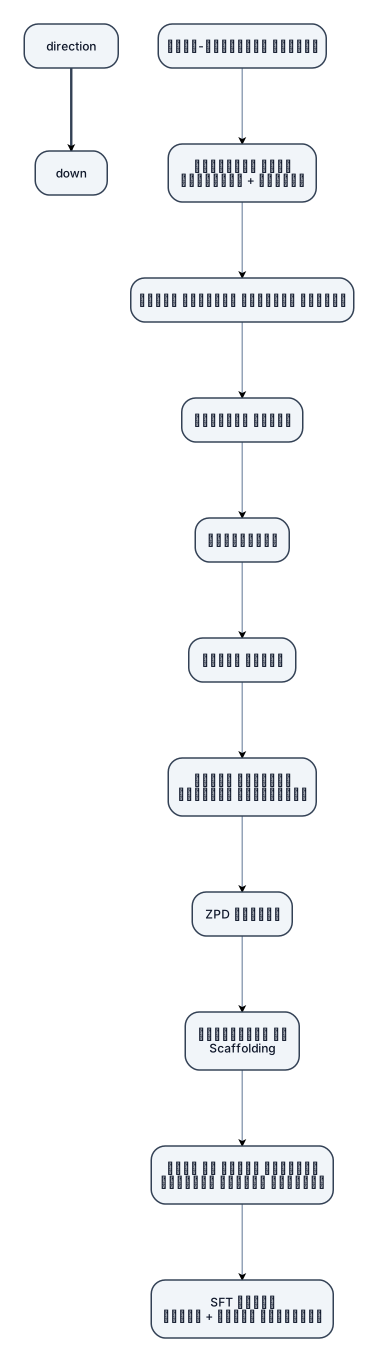
න්යායාත්මක රාමුව (Theoritical framework) සමාජ-ප්රජානන න්යාය ↓ පුද්ගලික සාධක හැසිරීම් + පරිසරය ↓ ස්වයං නියාමිත ඉගෙනුම් න්යාය ↓ සැලසුම් කිරීම ↓ නිරීක්ෂණය ↓ ස්වයං ඇගයීම ↓ ස්වයං නියාමිත ඉගෙනුම් උපායමාර්ග ↓ ZPD න්යාය ↓ මඟපෙන්වීම හා Scaffolding ↓ ගණිත හා භෞතික විද්යා ඉගෙනුම් අභියෝග ජයගැනීම ↓ SFT සාධනය (ගණිතය + භෞතික විද්යාව)
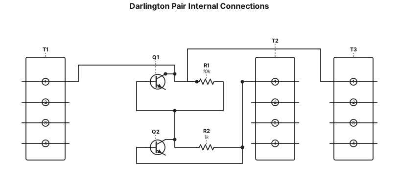
Draw the internal connections of Darlington pair.
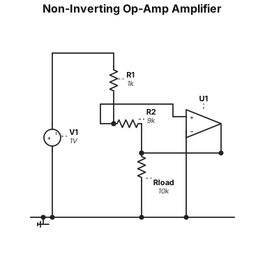
A non-inverting op-amp amplifier circuit with a gain of 10, using a 1 kΩ input resistor and a 9 kΩ feedback resistor
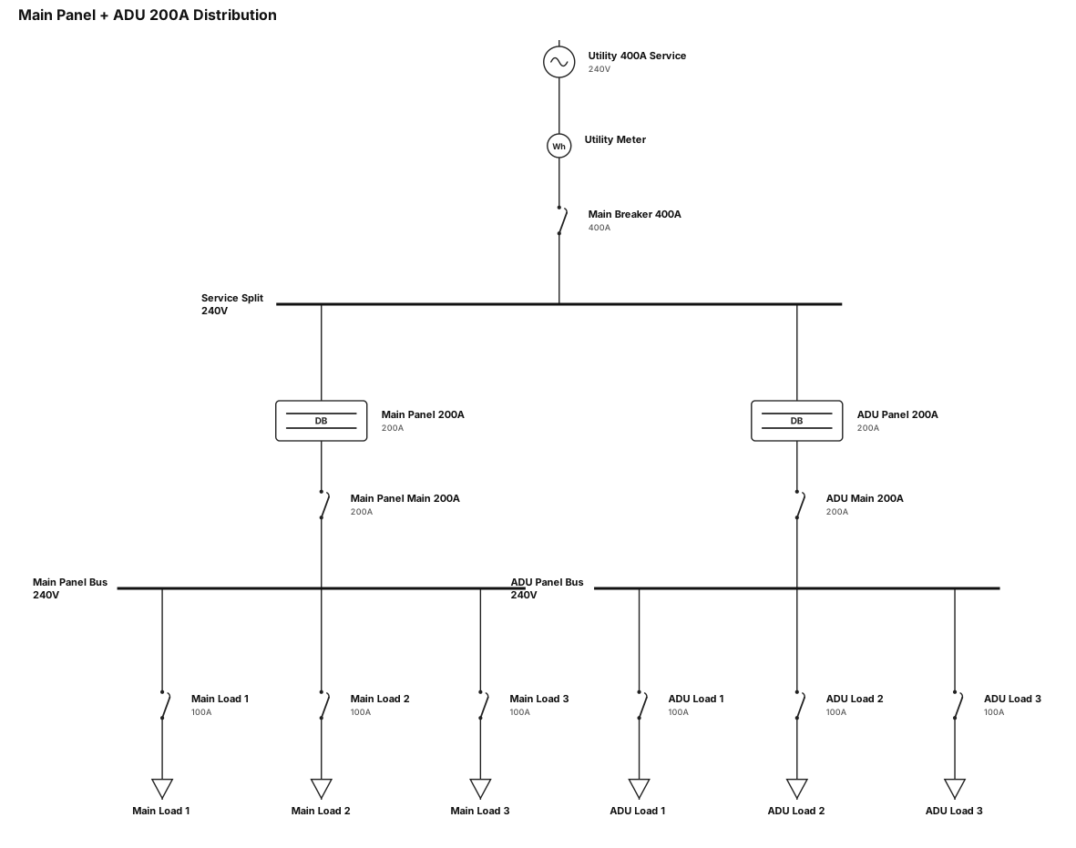
single line drawing for 100Amp to 400Amp 200A on main panel and 200A on the ADU
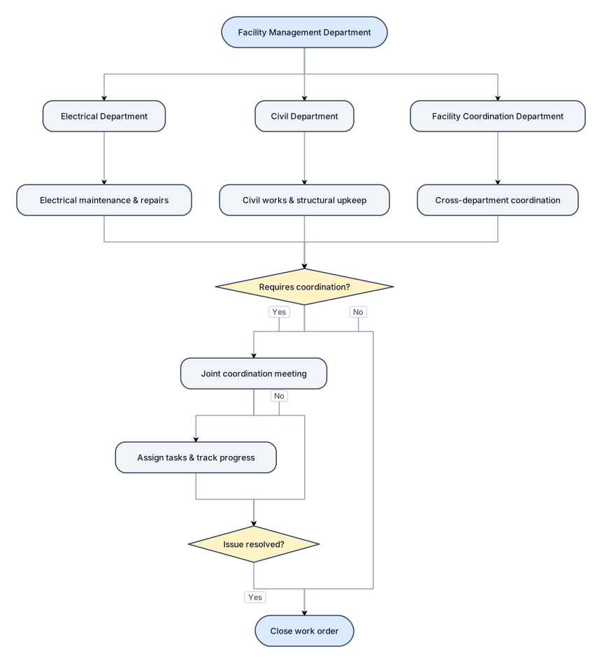
Facility Management Department with Electrical Civil Facility Cordination Departments as Branches
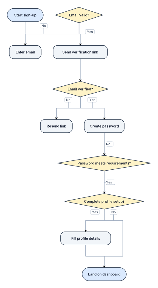
A flowchart for a user sign-up process: enter email, verify email, create password, optional profile setup, then land on the dashboard