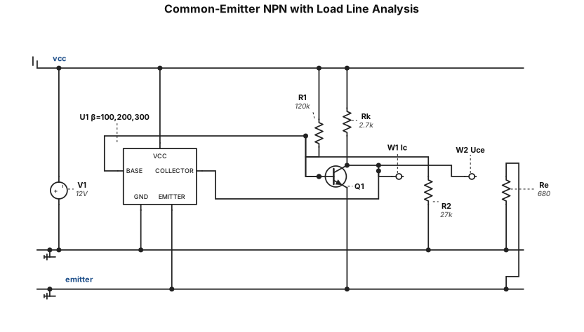
A technical engineering diagram on a white background with a faint light blue grid, combining a common-emitter NPN transistor circuit with an analytical chart and graph. The left side shows the circuit: a 12V DC source, base voltage divider with resistors R1=120kΩ and R2=27kΩ, an NPN transistor, collector resistor Rk=2.7kΩ, and emitter resistor Re=680Ω. To the right of the circuit, there is a small, neat data table listing three rows for beta (β) values: 100, 200, and 300, with columns for Ic and Uce. Below the table, a small conceptual load line graph (Vce vs Ic) highlights the operating Q-point. Clean vector style, monochromatic black lines for the circuit, professional educational layout, standard IEEE/IEC symbols.
NODE ARCHIVE · REAL DIAGRAM BRIEFS
Diagram Examples from Real Visitor Prompts
Browse eligible diagrams shared by FreeDiagram visitors, inspect the exact prompts, and build your own version.
Browse 3304 real creationsCOMMUNITY OUTPUTS · EXACT PROMPTS
All visitor creations
Showing 1873–1896 of 3304. No stock examples or system defaults. Choose a tool, study a real result, then reopen its prompt as your starting point.
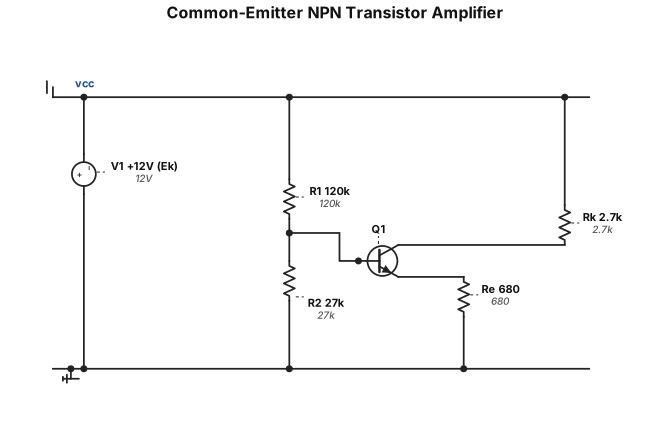
A clean, technical electronic circuit schematic of a common-emitter NPN transistor amplifier on a white background with a faint light blue grid. A top horizontal wire represents the power rail, connected to a DC source labeled 'V1 +12V (Ek)'. A bottom horizontal wire is connected to a ground symbol. A voltage divider consisting of two zigzag resistors, 'R1 120k' (top) and 'R2 27k' (bottom), is connected to the base of an NPN transistor labeled 'Q1'. A zigzag collector resistor 'Rk 2.7k' connects the top rail to the transistor's collector. A zigzag emitter resistor 'Re 680' connects the transistor's emitter to the bottom ground rail. Minimalist, professional engineering style, monochromatic black lines, standard IEEE/IEC symbols, neat layout.
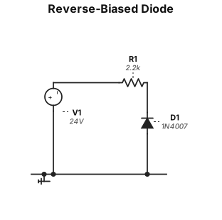
**Английский промт для генерации схемы обратного включения диода:** > *A clean, technical electronic circuit schematic based on image_3.png, presented on a white background with a subtle grid. A vertical DC voltage source is shown on the left, labeled 'V1 24V', with its negative terminal at the bottom connected to a solid ground line with a standard IEEE/IEC ground symbol. From the positive terminal of V1, a neat right-angle wire connects to a horizontal, zig-zag resistor symbol labeled 'R1 2.2 kΩ'. Following the resistor, a vertical wire extends downwards, connecting to a diode. Crucially, this diode (labeled 'D1 1N4007') is oriented with its cathode (the line-side of the triangle symbol) facing upwards, towards the source, representing reverse bias. The anode of D1 connects to the same ground line. All labels use clean, monochromatic technical typography.*
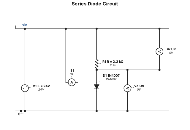
A clean, professional black and white electronic circuit schematic on a white background. Educational laboratory style. A DC voltage source labeled "E = 24V", connected in series to a resistor "R = 2.2 kΩ", and a silicon diode "1N4007" pointing right, ending in a ground symbol. Include a current arrow labeled "I" and voltage labels "Ud" and "UR". Standard IEEE/IEC symbols, minimalist, neat horizontal layout.
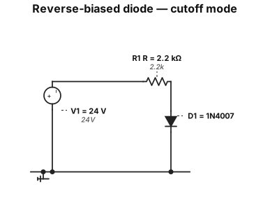
Create a clean educational electrical schematic on a white background using standard diode symbols. Show one simple series circuit: a 24 V DC voltage source, a 2.2 kΩ resistor, and a 1N4007 diode connected in series to ground. The diode must be reverse-biased. Rotate the diode 180 degrees compared with a forward-biased circuit: the cathode bar MUST be at the top, directly connected to the resistor and the positive side of the 24 V source; the anode MUST be at the bottom, connected toward ground. The cathode bar must be clearly visible above the diode symbol. Do not place the cathode bar near ground. Do not add any extra current source, parallel branch, measuring instrument, or additional wires. Show only one closed series loop. Label the components exactly: “V1 = 24 V” “R = 2.2 kΩ” “D1 = 1N4007” Add the text “Reverse-biased diode — cutoff mode”. Remove all unwanted labels, placeholder text, duplicate values, and text such as “Wlabel”. Use a neat technical style with black circuit lines, clear labels, and a white background.
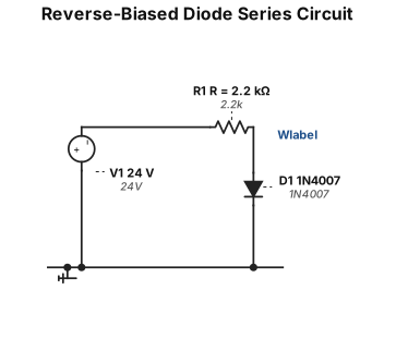
Create a clean educational electrical schematic on a white background using standard IEC circuit symbols. Show one simple series circuit only: a 24 V DC voltage source, a 2.2 kΩ resistor, and a 1N4007 diode connected in series to ground. The diode must be reverse-biased: connect the cathode, marked by the diode bar, toward the resistor and the positive terminal of the 24 V source; connect the anode toward ground. Do not add any extra current source, parallel branch, measuring instrument, or additional wires. Show only one closed series loop. Label the source “24 V”, the resistor “R = 2.2 kΩ”, and the diode “D1 1N4007”. Add a small label near the diode: “Reverse current ≈ 0, cutoff mode”. Use a neat horizontal layout, black circuit lines, clear technical labels, and no decorative elements.
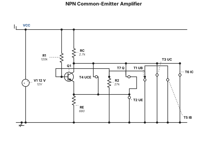
Create a clean educational circuit schematic on a white background using standard IEC symbols. Show an NPN transistor, such as a 2N3904 or BC547, in a common-emitter amplifier configuration. Use a 12 V DC power supply. Connect R1 = 120 kΩ from the positive supply to the transistor base and R2 = 27 kΩ from the base to ground. Connect the collector through R_C = 2.7 kΩ to the positive supply. Connect the emitter through R_E = 680 Ω to ground. Label the base, emitter, and collector voltages as U_B, U_E, and U_C. Also label U_CE, base current I_B, collector current I_C, and the operating point Q. Use straight wires, clear labels, black circuit lines, and no decorative background.
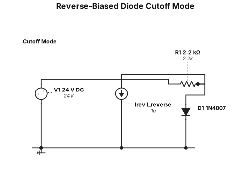
Create a clean educational electrical schematic on a white background using standard IEC circuit symbols. Show a 24 V DC voltage source, a 2.2 kΩ resistor, and a 1N4007 diode connected in series to ground, but reverse the diode polarity. Clearly show the cathode toward the voltage source and the anode toward ground. Mark the very small reverse current I_reverse and label the circuit state as “cutoff mode”. Use a black-and-white technical style with clear component labels and no decorative elements.
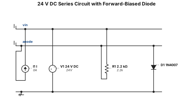
Create a clean educational electrical schematic on a white background using standard IEC circuit symbols. Show a 24 V DC voltage source connected in series to a 2.2 kΩ resistor, then to a silicon 1N4007 diode, and finally to ground. The diode must be forward-biased, with the anode connected toward the resistor and the cathode connected toward ground. Mark the current direction with an arrow and label the voltage across the diode as U_D and the voltage across the resistor as U_R. Use a neat horizontal layout, black circuit lines, clear technical labels, and no decorative elements.
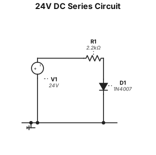
Create a clean educational electrical schematic on a white background using standard IEC circuit symbols. Show a 24 V DC voltage source connected in series to a 2.2 kΩ resistor, then to a silicon 1N4007 diode, and finally to ground. The diode must be forward-biased, with the anode connected toward the resistor and the cathode connected toward ground. Mark the current direction with an arrow and label the voltage across the diode as U_D and the voltage across the resistor as U_R. Use a neat horizontal layout, black circuit lines, clear technical labels, and no decorative elements.
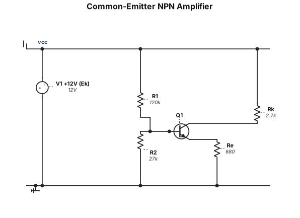
A clean, professional electronic circuit schematic of a common-emitter NPN transistor amplifier. Top rail is labeled "+12V (Ek)". A voltage divider with resistors R1 (120k) and R2 (27k) is connected to the base of the NPN transistor. Collector resistor Rk (2.7k) connects the collector to the +12V rail. Emitter resistor Re (680 Ω) connects the emitter to ground. Standard IEEE electrical symbols, monochromatic, technical drawing style, white background.

hur kommer det sig att så många fastnar i låtskrivningsprocessen och står med flertal ofärdiga låtskissar, låtidéer osv?
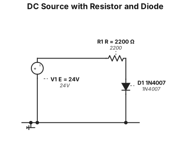
A clean, professional black and white electronic circuit schematic on a white background. The circuit consists of a single loop. On the left, a DC voltage source labeled "E = 24V". Connected in series clockwise: a resistor on the top labeled "R = 2200 Ω", a standard semiconductor diode on the right side pointing downwards labeled "1N4007", and a ground symbol at the bottom negative return path. Standard IEEE/IEC electrical symbols, minimalist, high contrast.

en flowchart med olika tänkbara vägar scenarior i en låtskrivningsprocess

A flowchart for a songwriting process

A flowchart for music theory

A product roadmap timeline for a mobile app launch from Q1 to Q4 with milestones
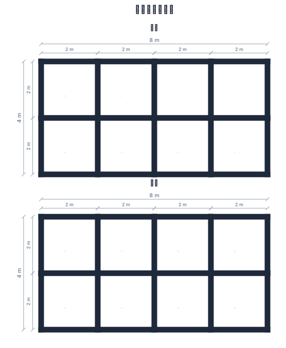
請幫我設計上下兩層,每層細分成8個正方體,短邊2個、長邊4個
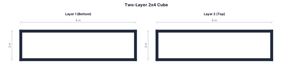
請幫我設計兩層 每層2*4的正方體
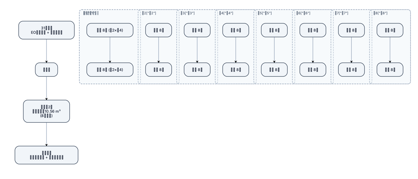
7.4.3.1 共31個點位放置EO指示標籤及生物指示劑,每一層體積為0.66 m3,共8台車,每台車2層產品體積約為10.56m3至少評估,此次執行滲透驗證包含8台車滿載,點位包含四周上下點位及每台車中心點,共計31個點位。 箱體為寬2個*長4個 兩層
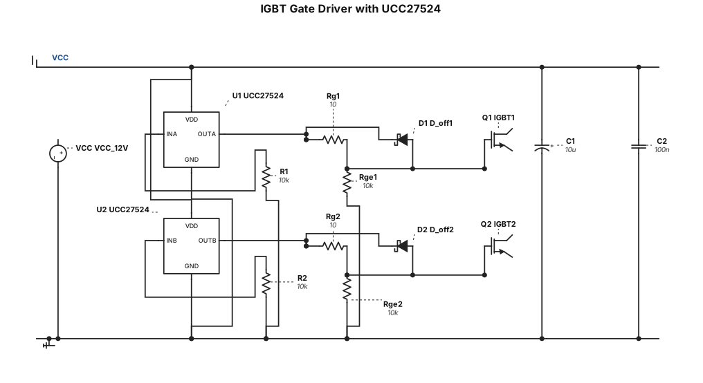
i have to make one circuit using UCC27524 for my IGBT driving applications, suggest circuit
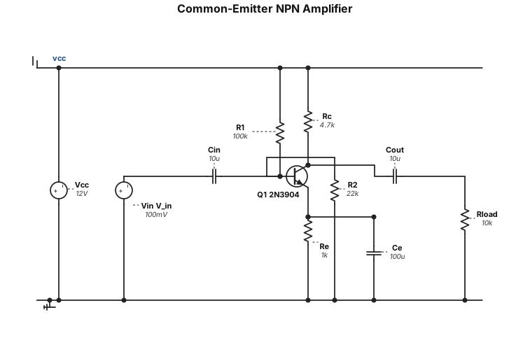
A common-emitter NPN transistor amplifier circuit
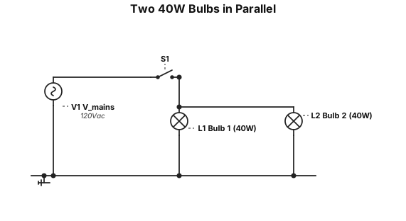
two 40 watt light bulbs connected in parallel in light fixture, powered by 120v of electricity for 150 hours at $0.12 per Kw-hr
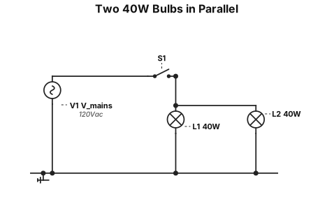

two 40 watt light bulbs connected in parallel in light fixture, powered by 120v of electricity