
i want 3 big blocks and 4 small blocks
NODE ARCHIVE · REAL DIAGRAM BRIEFS
Diagram Examples from Real Visitor Prompts
Browse eligible diagrams shared by FreeDiagram visitors, inspect the exact prompts, and build your own version.
Browse 3261 real creationsCOMMUNITY OUTPUTS · EXACT PROMPTS
All visitor creations
Showing 169–192 of 3261. No stock examples or system defaults. Choose a tool, study a real result, then reopen its prompt as your starting point.
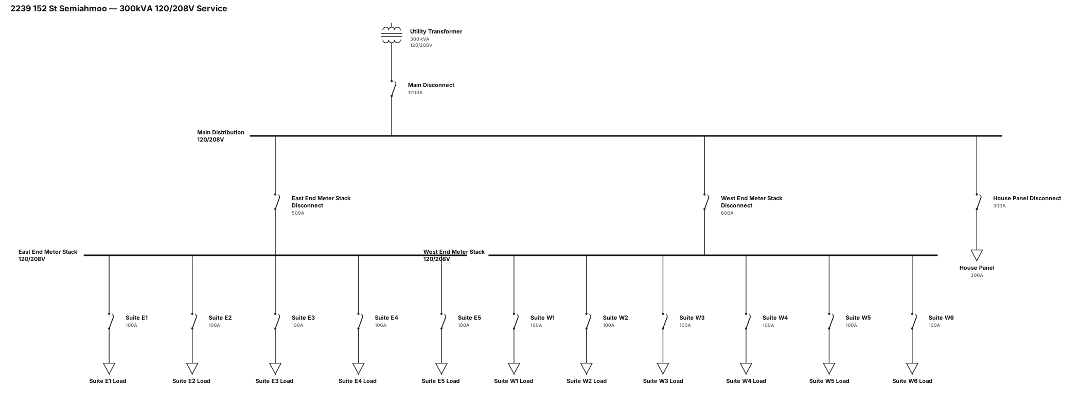
A single-line diagram for 2239 152 St Semiahmoo : 300kVA 120/208V three phase transformer to a 1200A main disconnect, split into three separate disconnects (one for 300A house panel, one for 500A East End Meter Stack, one for 600A West End Meter Stack). Each meter stack has 100A disconnects for each of the suites
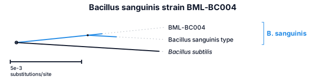
Bacillus sanguinis strain BML-BC004
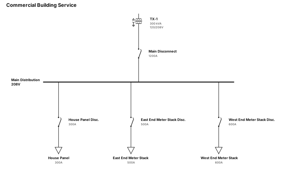
A single-line diagram for a commercial building: 300kVA 120/208V three phase transformer to a 1200A main disconnect, split into three separate disconnects (one for 300A house panel, one for 500A East End Meter Stack, one for 600A West End Meter Stack)
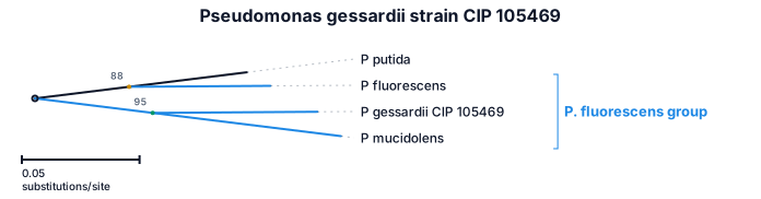
Pseudomonas gessardii strain CIP 105469
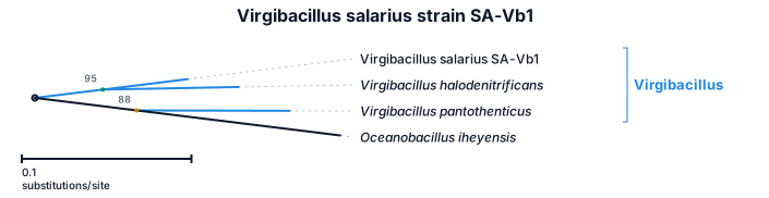
Virgibacillus salarius strain SA-Vb1
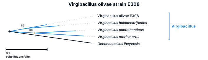
Virgibacillus olivae strain E308
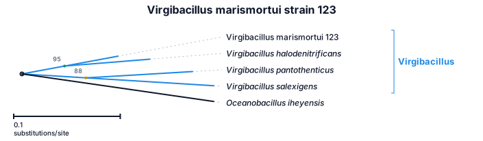
Virgibacillus marismortui strain 123
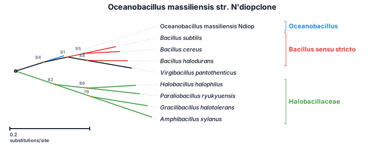
Oceanobacillus massiliensis str. N'diopclone
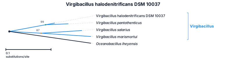
Virgibacillus halodenitrificans strain DSM 10037
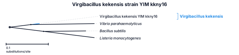
Virgibacillus kekensis strain YIM kkny16
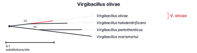
Virgibacillus olivae
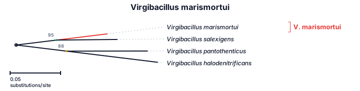
Virgibacillus marismortui
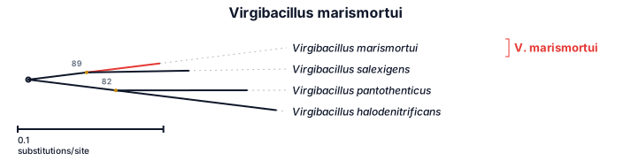
Virgibacillus marismortui
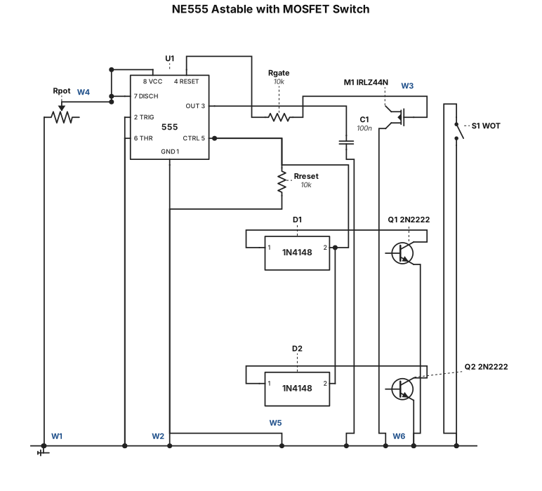
NE555 timer astable circuit with MOSFET switch. Components: NE555 IC (8-pin), IRLZ44N N-MOSFET, two 2N2222 NPN transistors, four 1N4148 diodes, one WOT switch. 555 pins 2+6 to 47k pot and 100nF cap. Pin 3 through 10k to MOSFET gate. Pin 4 pulled to 5V through 10k, two diodes from transistor collectors into pin 4. MOSFET drain to IGT_IN, source to IGT_OUT and GND.
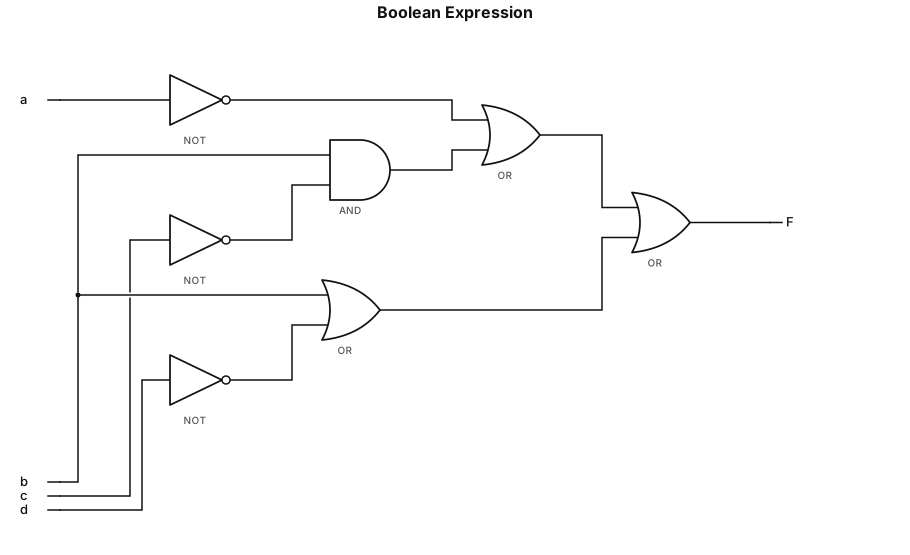
F = (a' + (b * c')) + (b + d')
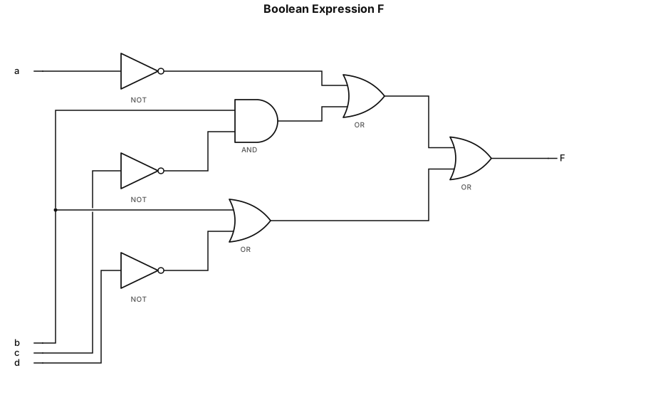
The given Boolean expression is: \[ F=(a'\lor(b\land c'))\lor(b\lor d') \] The circuit in the provided answer is roughly correct in concept, but the final gate connections are unclear.
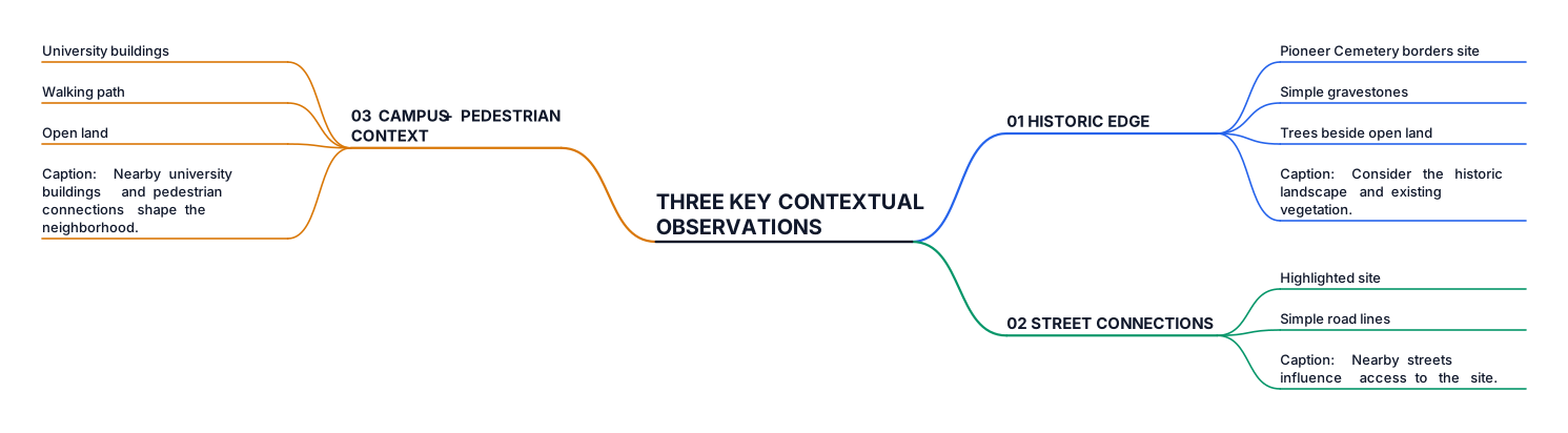
Create a clean, professional architecture presentation diagram titled “THREE KEY CONTEXTUAL OBSERVATIONS.” Organize three numbered sections side by side, not as a branching mind map. 01 HISTORIC EDGE — Pioneer Cemetery borders the project site. Show simple gravestones and trees beside open land. Caption: “Consider the historic landscape and existing vegetation.” 02 STREET CONNECTIONS — Show a highlighted site surrounded by simple road lines. Caption: “Nearby streets influence access to the site.” 03 CAMPUS + PEDESTRIAN CONTEXT — Show university buildings, a walking path, and open land. Caption: “Nearby university buildings and pedestrian connections shape the neighborhood.” Use a white background, muted sage green, dark blue, and beige. Use simple architectural line drawings and minimal text. Make it suitable for an architecture school site-analysis board.
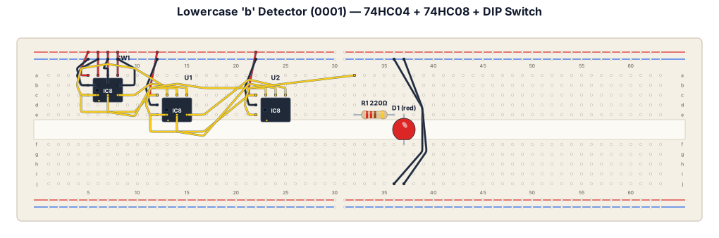
# TINKERCAD CIRCUIT: LOWERCASE LETTER “b” DETECTOR USING ONE LED Create a technically accurate Tinkercad Circuits breadboard project using TWO breadboards, one 74HC04 NOT-gate IC, exactly one 74HC08 AND-gate IC, a four-position DIP switch, and ONLY ONE physical LED as the output indicator. The purpose of the circuit is to detect the four-bit input code assigned to lowercase letter “b.” The single LED must turn ON only when the input is 0001 and remain OFF for all other input combinations. Do not use seven LEDs or a seven-segment display. Do not use an Arduino or a microcontroller. Use physical NOT and AND logic gates.
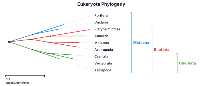
A phylogenetic tree of the following eukaryota, meatazoa, porifera, cnidaria, bilateria, anelida, platthelyminthes, mollusca, arthropoda, tetrapoda, craniota, vertrebrata,
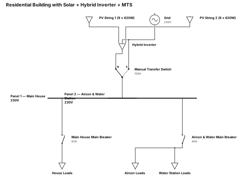
A single-line diagram for a residential building. Solar panels 620W each connected in series up to 9 panels each line. Then hybrid inverter is connected to the normal side of MTS, the grid is connected to the other side of MTS. Then output of MTS is connected to panel 1 (main house), and panel 2 (aircon and water station). Grid is also connected to the hybrid inverter.
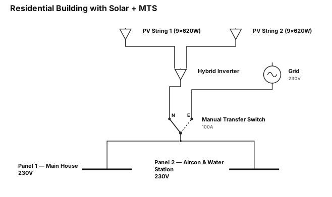
A single-line diagram for a residential building. Solar panels 620W each connected in series up to 9 panels each line. Then hybrid inverter is connected to the normal side of MTS, the grid is connected to the other side of MTS. Then output of MTS is connected to panel 1 (main house), and panel 2 (aircon and water station)
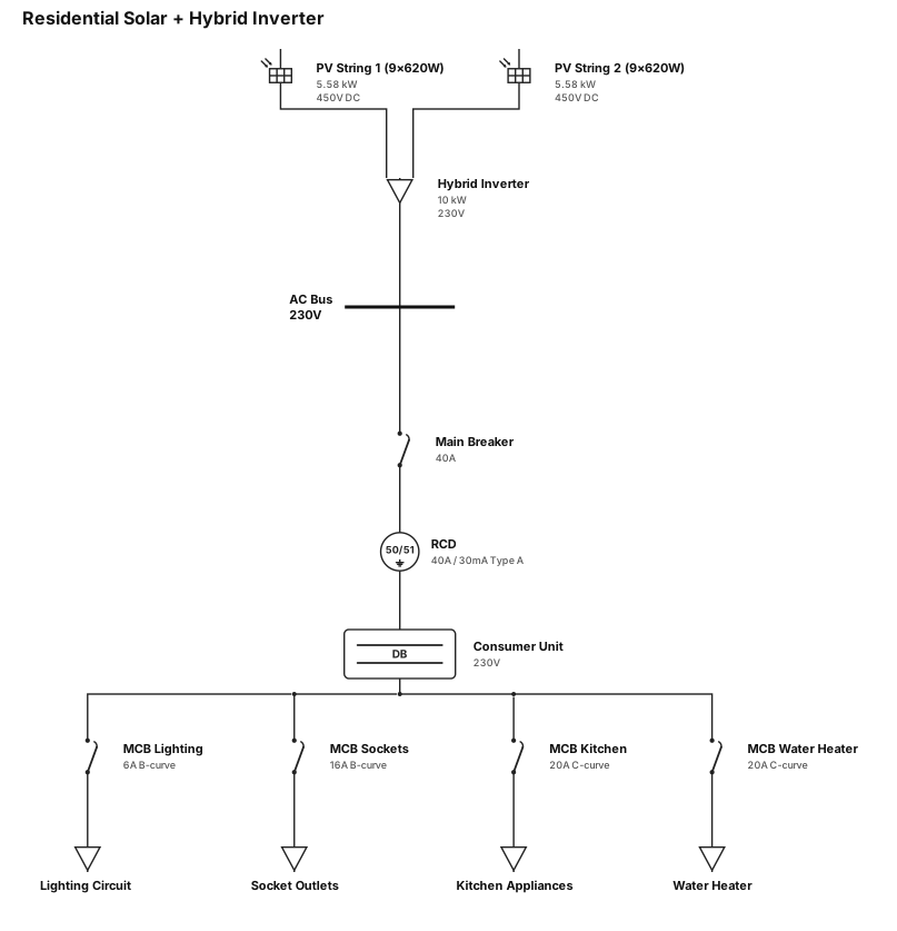
A single-line diagram for a residential building. Solar panels 620W each connected in series up to 9 panels each line. Then hybrid inverter is connected to the home loads
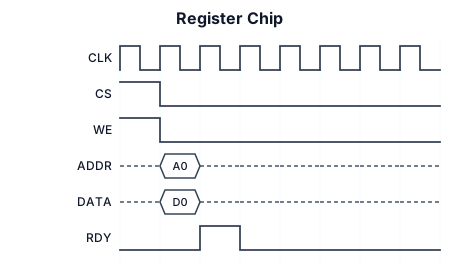
A timing diagram for Register Chip