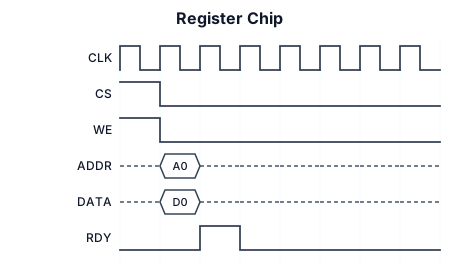
A timing diagram for Register Chip
NODE ARCHIVE · REAL DIAGRAM BRIEFS
Diagram Examples from Real Visitor Prompts
Browse eligible diagrams shared by FreeDiagram visitors, inspect the exact prompts, and build your own version.
Browse 3262 real creationsCOMMUNITY OUTPUTS · EXACT PROMPTS
All visitor creations
Showing 193–216 of 3262. No stock examples or system defaults. Choose a tool, study a real result, then reopen its prompt as your starting point.
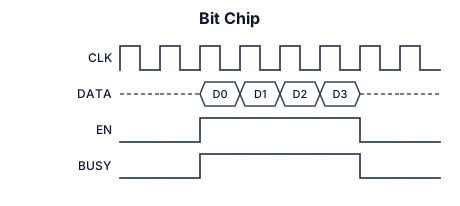
A timing diagram for Bit Chip
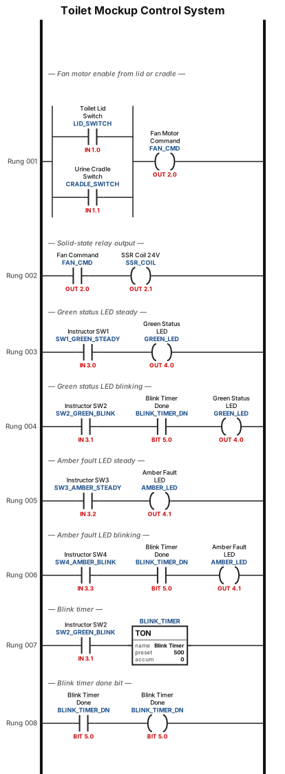
A control wiring and logic diagram for a toilet mockup system: opening the toilet lid switch or lifting the urine cradle switch commands an Arduino to energize a 24V fan motor through a solid-state relay, while a 4-switch instructor box sets the Green status and Amber fault LEDs to steady, blinking or off states, powered by isolated 5V logic and 24V motor power rails.
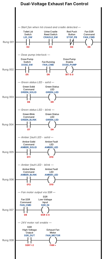
This system diagram illustrates a dual-voltage electrical control architecture centered around an microcontroller and a DC power supply. The power supply is divided into two galvanically isolated domains: a low-voltage 5VDC that powers the Arduino board's 5V/GND header pins and the UBL 1100 4-Switch Box, and a high-voltage +24 VDC motor rail (Channel 1) dedicated solely to running a heavy-duty exhaust fan . At the center, four dry-contact field switches on the toilet mockup the toilet lid switch (D2), urine cradle reed switch (D3), red push button (D4), and dose pump switch (D5) connect between their designated Arduino digital pins and a shared 5VDC common ground bus. The UBL 1100 instructor switch box sends four active-high signal wires into Arduino pins D6 (Green Solid), D7 (Green Blink), D11 (Amber Solid), and D12 (Amber Blink), which dynamically command a Green Status LED on pin D9 (via a series 330" " Ωresistor) and an Amber Fault LED on pin D10 (via a series 510" " Ωresistor) [1]. Completing the high-power circuit, Arduino output pin D8 and GND connect across the low-voltage input terminals (Pins 3 & 4) of a DC-to-DC Solid-State Relay (SSR), while the relay's high-voltage output terminals (Pins 1 & 2) switch the continuous +24.0" V DC" power feed to the Red wire (FAN +) of the fan motor, whose Black wire (FAN -) returns directly to the isolated 24" V" power supply ground.
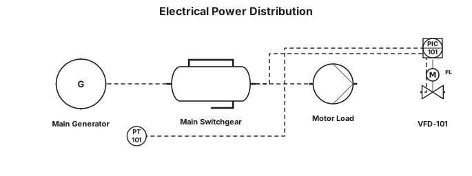
i need electrical diagram
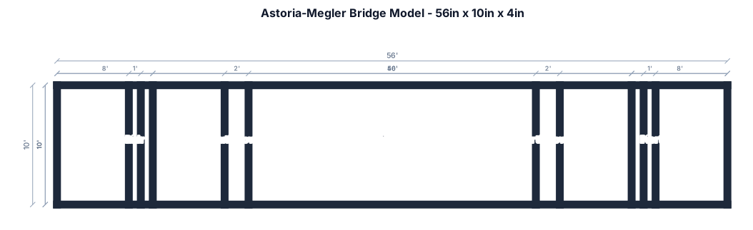
56 inch long 10 inch tall 4 inch wide model of Astoria Megler bridge
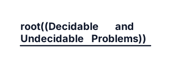
Create a colorful, well-organized academic mind map on “Decidable and Undecidable Problems” for Theory of Computation. Central topic: Decidable and Undecidable Problems. Main branches: 1. Decidable Problems — definition, recursive languages, DFA acceptance, DFA emptiness, DFA equivalence. 2. Undecidable Problems — definition, Halting Problem, Post Correspondence Problem (PCP), CFG ambiguity. 3. Halting Problem — meaning, Turing Machine, why it is undecidable. 4. Comparison — whether an algorithm exists, whether it always halts, examples. 5. Importance — limits of computation, algorithm analysis, program verification. Use short keywords, clear sub-branches, different colors, readable labels, connecting lines, and a landscape layout. Make it suitable for a college assignment and export as a high-quality PNG.
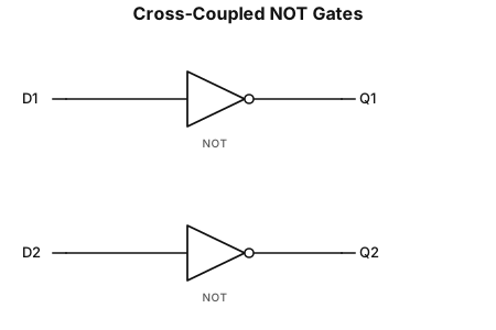
A logic gate circuit 2 inputs D1 D2 connected with 2 different not gates with each one one output Q1 Q2. the output of D1 goes as input of D2 and viceversa
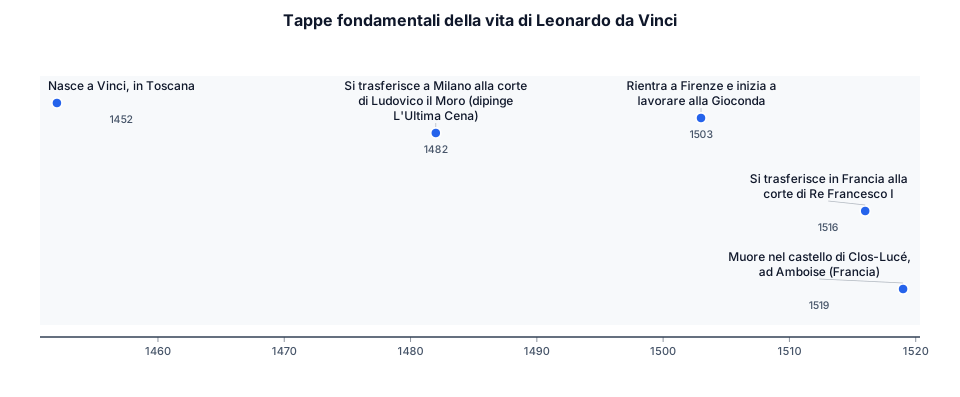
timeline title Tappe fondamentali della vita di Leonardo da Vinci 1452 : Nasce a Vinci, in Toscana 1482 : Si trasferisce a Milano alla corte di Ludovico il Moro (dipinge L'Ultima Cena) 1503 : Rientra a Firenze e inizia a lavorare alla Gioconda 1516 : Si trasferisce in Francia alla corte di Re Francesco I 1519 : Muore nel castello di Clos-Lucé, ad Amboise (Francia)
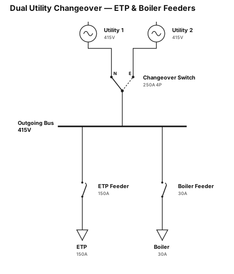
a 4 pole 250 a change over switch . input power source utility 1 and utility 2 outgoing feeder etp 150 a and boiler 30 a
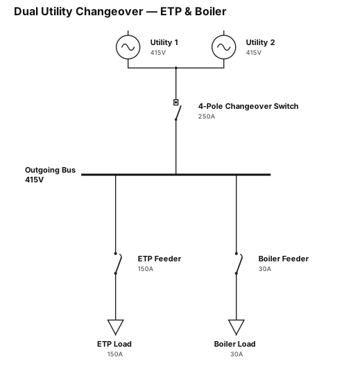
A 4 pole change over switch 250 a input power from two source utility 1 and utility 2 out going feeder etp 150a and boiler 30 a.
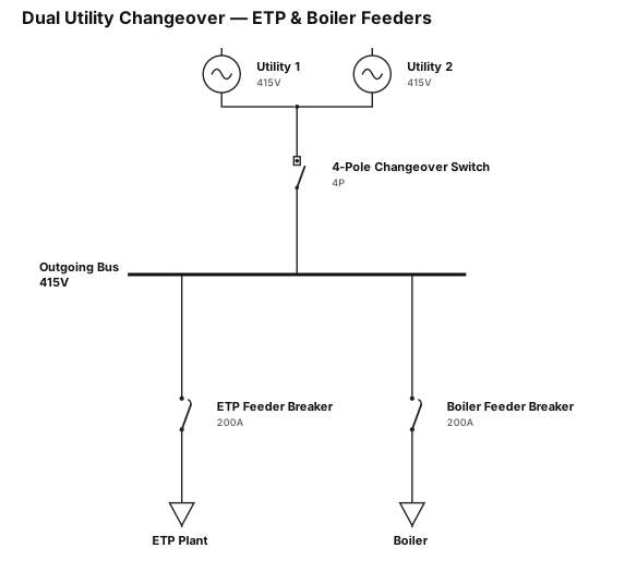
A 4 pole change over switch input power from two source utility 1 and utility 2 out going feeder etp and boiler .
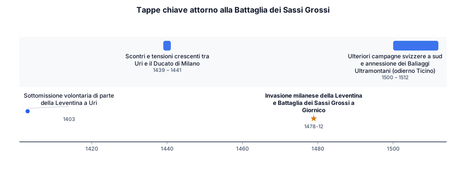
timeline title Tappe chiave attorno alla Battaglia dei Sassi Grossi 1403 : Sottomissione volontaria di parte della Leventina a Uri 1439 - 1441 : Scontri e tensioni crescenti tra Uri e il Ducato di Milano 1478 (Dicembre) : Invasione milanese della Leventina e Battaglia dei Sassi Grossi a Giornico 1500 - 1512 : Ulteriori campagne svizzere a sud e annessione dei Baliaggi Ultramontani (odierno Ticino)
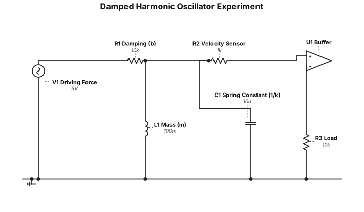
a set up for a damped harmonic oscillator experiment using springs
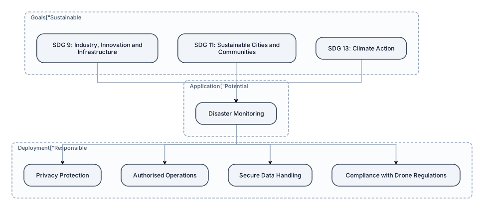
Sustainable Development Goals SDG 9: Industry, Innovation and Infrastructure SDG 11: Sustainable Cities and Communities SDG 13: Climate Action — potential application in disaster monitoring Responsible Deployment: Privacy protection, authorised operations, secure data handling and compliance with applicable drone regulations. cereate a flow diagram for this
Challenges in Conventional Surveillance Continuous manual monitoring of live video feeds is time-consuming. Important events may be missed during prolonged surveillance. Internet-dependent AI systems may fail in low-connectivity areas. Limited battery life and payload capacity restrict mission duration. Conventional drones generally provide footage without intelligent, real-time analysis. Need: An intelligent, reliable and cost-conscious surveillance solution that converts live video into actionable information.
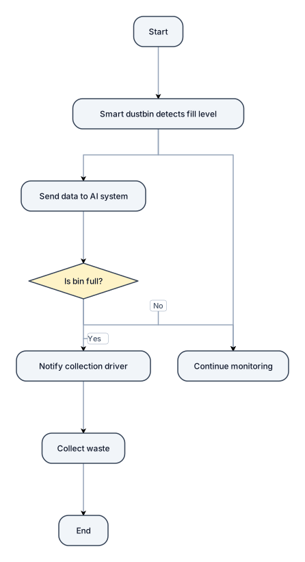
Create a simple flowchart for an AI-based smart waste management system. Show how a smart dustbin detects its fill level, sends data to an AI system, and decides whether waste collection is needed. If the bin is full, notify the collection driver and collect the waste. If it is not full, continue monitoring. Use clear shapes, arrows, and Yes/No labels.

An org chart for a 18-people. with the SVP as the head. Director customer relation reports to SVP. Director CR has 5 people under him. in that 5 people 2 of them have people under them. Director CSR also reports to Commercial Director who has another person reporting to him and he has 5 people under him.
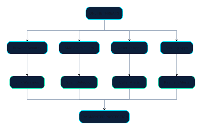
Create a clean, professional cybersecurity flow diagram titled **“EXISTING SOLUTIONS”** for a hackathon presentation. Show this exact visual flow: TOP: “ONLINE THREATS” ↓ Four parallel branches: 1. Browser Security → Link Warnings 2. SMS Spam Filters → Spam Detection 3. Caller ID Apps → Caller Alerts 4. Banking Apps → Payment Alerts Bring all four branches together at the bottom: “FRAGMENTED PROTECTION” Design requirements: - Use only diagrams, arrows, icons, and short labels. - No paragraphs or explanatory text. - Dark navy background, cyan and teal accents, white labels. - Use a neat top-to-bottom flowchart with four evenly spaced branches. - Use simple editable Canva shapes and line icons. - Keep all elements aligned, readable, and uncluttered. - 16:9 landscape canvas. - Make the diagram visually explain that existing tools protect different areas separately.

Create a professional engineering block diagram for a Triple-Tap Activated Smart Safety Ring for Emergency Alert and Location Sharing. Show these blocks connected with directional arrows: 1. Triple-tap input 2. Accelerometer / tap sensor 3. Microcontroller with tap-count and timing validation 4. Bluetooth Low Energy (BLE) communication 5. Smartphone companion application 6. Smartphone GPS / location services 7. Trusted emergency contacts receiving an SOS alert with location 8. LED and vibration motor for confirmation 9. Rechargeable battery and USB charging circuit powering the ring Show the main emergency signal flow clearly. Separate the power supply path from the data communication path. Use standard engineering block-diagram symbols, clean labels, a white background, neat arrows, and a professional academic project style. Do not invent components or show a direct police connection as a guaranteed feature. Label it as a conceptual prototype diagram.
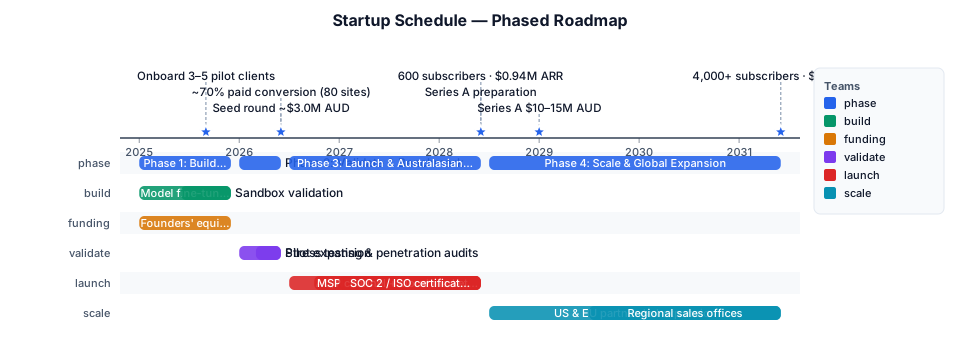
A time line for startup schedule in phases Phase 1: Build & Prototype Months 1–12 (8–12 Mos) Focus: Model fine-tuning, dashboard development, and initial sandbox validation. Key Milestones: Onboard 3–5 non-paying pilot clients (e.g., local legal practices, regional clinics). Funding Strategy: Founders' equity, university commercialization grants, and R&D tax incentives. Phase 2: Validate & Benchmark Months 13–18 (6 Mos) Focus: Technical stress testing, third-party penetration audits, and pilot expansion. Key Milestones: Convert early adopters to paid tiers; achieve ~70% paid conversion across 80 pilot sites. Funding Strategy: Seed Investment Round (~$3.0M AUD). Phase 3: Launch & Australasian Rollout Months 19–36 (1.5 Yrs) Focus: Commercial release across Australia & New Zealand, MSP channel program, cloud marketplace listings (AWS/Azure), and SOC 2 / ISO certifications. Key Milestones: Reach 600 active paying subscribers and $0.94M AUD ARR. Funding Strategy: Organic SaaS revenue supplemented by Series A preparation at Phase exit. Phase 4: Scale & Global Expansion Months 37–72 (3 Yrs) Focus: Partner-led expansion into US and EU territories; demand-driven establishment of regional sales offices. Key Milestones: Expand customer base to 4,000+ paying subscribers and $6.2M AUD ARR. Funding Strategy: Series A Investment Round ($10.0M–$15.0M AUD).

Gannt chart I plan to finish the whole project in about 7 weeks, including the project proposal and the final report. This is a realistic and predictable time frame. The table below shows my plan.I plan to finish the whole project in about 8 weeks, including the project proposal and the final report. This is a realistic and predictable time frame. The table below shows my plan.
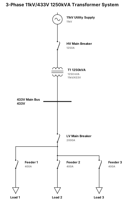
3 pss 11kv /433v 1250KVA transformer and 433v

1. Importance of Storages in Chemical Processing Units, Associated Safety Aspects & Accident Reduction [5 Marks] 1. Operational Importance: Bulk chemical storage serves as the vital operational buffer in processing plants, stabilizing raw material feed rates and absorbing output surges. 2. Associated Storage Hazards: Bulk containment concentrates massive chemical potential energy, presenting severe risks of BLEVE (Boiling Liquid Expanding Vapor Explosion), VCE (Vapor Cloud Explosion), pool fires, and toxic gas release. 3. Inherent Safety Design: Selection of tank type dictated by True Vapour Pressure (TVP < 1.5 psia = Fixed Cone Roof; 1.5 to 11.1 psia = Floating Roof; > 11.1 psia = Pressure Vessels/Bullets). 4. Engineering Safeguards: 110% net dyke secondary containment, PVRVs (+2.5/-0.5 mbar), Nitrogen blanketing (O2 < 5%), High-High Level Switches (LAHH @ 95% interlocked to ESDVs), and earthing clamps (R < 10 Ohms). 5. Accident Reduction: Implementing automated interlocks, non-destructive testing (NDT), and strict Permit-to-Work (PTW) protocols reduces chemical storage accidents by over 90%.