
Haz una línea de tiempo de la evolución del marketing
NODE ARCHIVE · REAL DIAGRAM BRIEFS
Diagram Examples from Real Visitor Prompts
Browse eligible diagrams shared by FreeDiagram visitors, inspect the exact prompts, and build your own version.
Browse 3312 real creationsCOMMUNITY OUTPUTS · EXACT PROMPTS
All visitor creations
Showing 1993–2016 of 3312. No stock examples or system defaults. Choose a tool, study a real result, then reopen its prompt as your starting point.
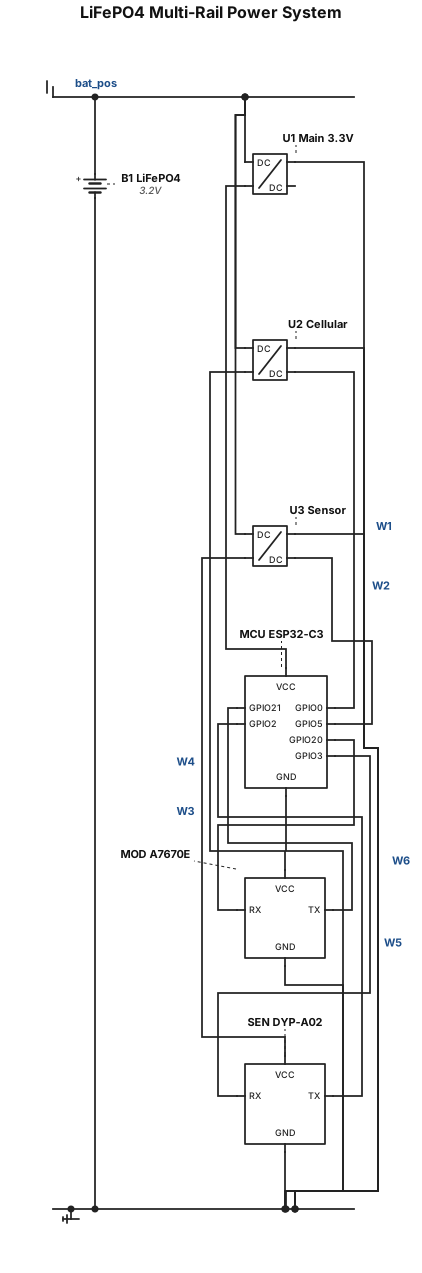
Component List: B1: LiFePO4 Battery 3.2v U1: Main 3.3V Boost Converter U2: Booster 1 (Cellular Power) U3: Booster 2 (Sensor Power) MCU: ESP32-C3 SuperMini MOD: A7670E Cellular Module SEN: DYP-A02 Sensor Power Wiring: B1 Positive -> U1 VIN B1 Positive -> U2 VIN B1 Positive -> U3 VIN U1 VOUT -> MCU VCC U2 VOUT -> MOD VCC U3 VOUT -> SEN VCC Ground Wiring (Common Ground): B1 Negative -> Common GND U1 GND -> Common GND U2 GND -> Common GND U3 GND -> Common GND MCU GND -> Common GND MOD GND -> Common GND SEN GND -> Common GND Control Logic (Enable Pins): MCU GPIO 0 -> U2 EN MCU GPIO 5 -> U3 EN UART Data Wiring: MCU GPIO 20 -> MOD RX MCU GPIO 21 -> MOD TX MCU GPIO 2 -> SEN TX MCU GPIO 3 -> SEN RX
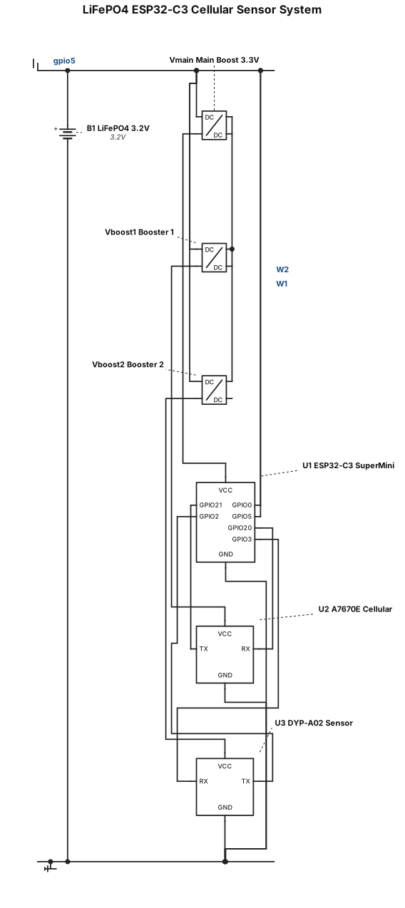
Hardware Components List 1x 3.2V LiFePO4 Battery 1x ESP32-C3 SuperMini 1x Main 3.3V Boost Converter (Always-on) 2x Switched Boost Converters (Booster 1 and Booster 2) 1x A7670E Cellular Module 1x DYP-A02 Sensor Wiring & Connections Power (VIN & GND) LiFePO4 Battery Positive (+) connects to the VIN of the Main 3.3V Boost Converter, Booster 1, and Booster 2. LiFePO4 Battery Negative (-) connects to a Common Ground bus. Common Ground connects to the GND pins of the ESP32-C3, all three Boost Converters, the A7670E, and the DYP-A02. Power Distribution (VOUT) Main 3.3V Boost Converter VOUT connects to ESP32-C3 VIN/VCC (Always-on power). Booster 1 VOUT connects to A7670E VCC (Duty-cycled power). Booster 2 VOUT connects to DYP-A02 VCC (Duty-cycled power). Control Pins (Enable Lines) ESP32-C3 GPIO 0 connects to Booster 1 EN (Enable). ESP32-C3 GPIO 5 connects to Booster 2 EN (Enable). Data Pins (UART Communication) ESP32-C3 GPIO 20 connects to A7670E RX. ESP32-C3 GPIO 21 connects to A7670E TX. ESP32-C3 GPIO 2 connects to DYP-A02 TX. ESP32-C3 GPIO 3 connects to DYP-A02 RX.
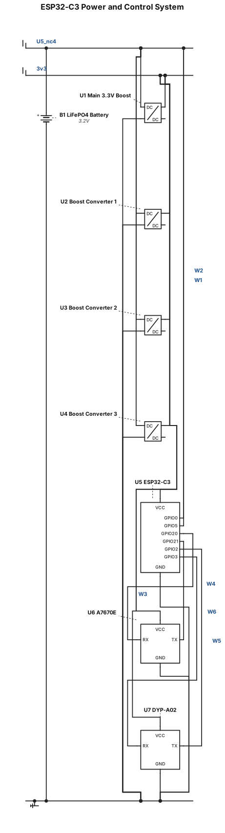
1. Power Connections LiFePO4 Battery (+ Terminal) Connects to VIN of the Main 3.3V Boost Converter. Connects in parallel to VIN of Boost Converter 1, Boost Converter 2, and Boost Converter 3. Ground (GND) Battery (-) connects to a Common Ground wire/bus. ESP32-C3 GND \rightarrow Common Ground. A7670E GND \rightarrow Common Ground. DYP-A02 GND \rightarrow Common Ground. All Boost Converter GND pins \rightarrow Common Ground. 2. Control Lines (Enable Pins) ESP32-C3 GPIO 0 \rightarrow EN (Enable) pin of Boost Converter 1 ESP32-C3 GPIO 5 \rightarrow EN (Enable) pin of Boost Converter 2 (Note: Booster 3 EN is unassigned here or wired permanently ON). 3. Data / Communication Lines (UART) A7670E Cellular Module: ESP32-C3 GPIO 20 \rightarrow A7670E RX pin ESP32-C3 GPIO 21 \rightarrow A7670E TX pin DYP-A02 Ultrasonic Sensor: ESP32-C3 GPIO 2 \rightarrow DYP-A02 TX pin ESP32-C3 GPIO 3 \rightarrow DYP-A02 RX pin
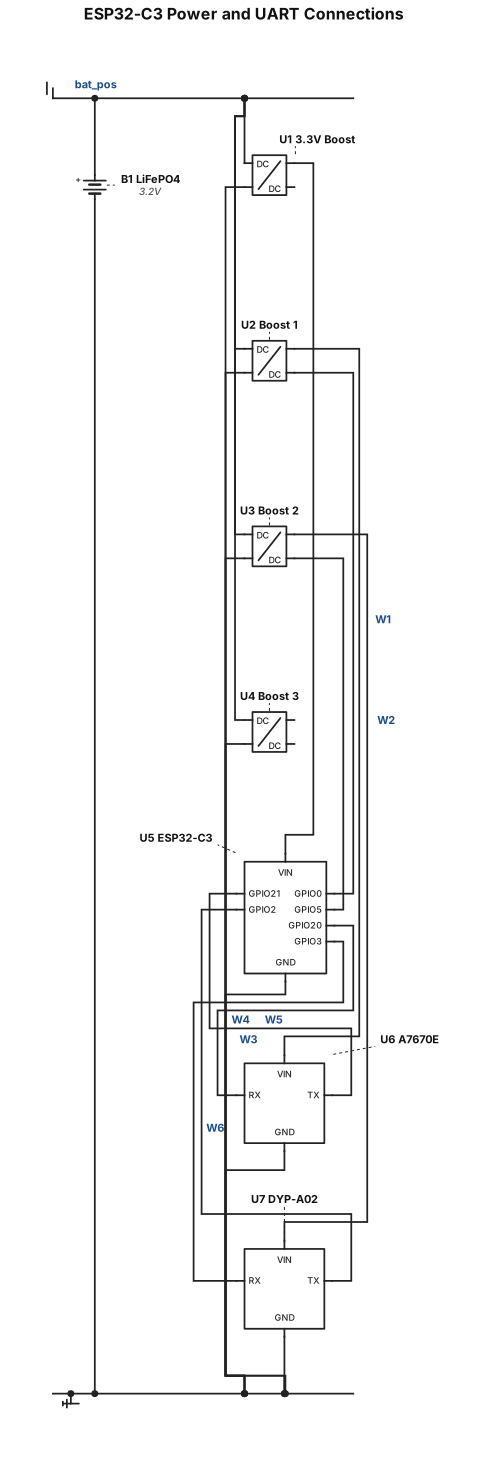
Power & Supply * LiFePO4 Battery 3.2v (+) > VIN of 3.3V Boost Converter & VIN of 1, 2 & 3 boost converters * Common Ground > Shared across all components (ESP32-C3, battery, boost converters, A7670E, DYP-A02) * Boost Converter Enable (EN) Pins * ESP32-C3 GPIO 0 > Booster 1 EN * ESP32-C3 GPIO 5 > Booster 2 EN * A7670E Cellular Module (UART) * ESP32-C3 GPIO 20 > A7670E RX * ESP32-C3 GPIO 21 > A7670E TX * DYP-A02 Sensor (UART) * ESP32-C3 GPIO 2 > DYP-A02 TX * ESP32-C3 GPIO 3 > DYP-A02 RX
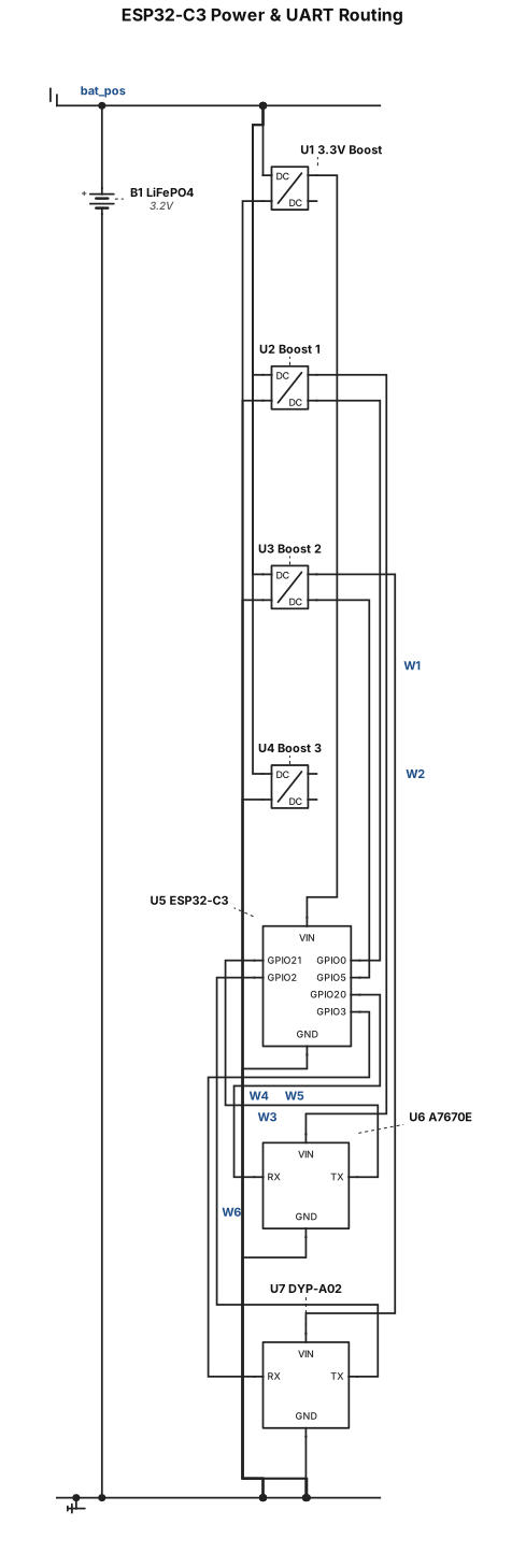
Power & Supply * LiFePO4 Battery 3.2v (+) to VIN of 3.3V Boost Converter & VIN of 3 boost converters * Common Ground to Shared across all components (ESP32-C3, battery, boost converters, A7670E, DYP-A02) * Boost Converter Enable (EN) Pins * ESP32-C3 GPIO 0 > Booster 1 EN * ESP32-C3 GPIO 5 > Booster 2 EN * A7670E Cellular Module (UART) * ESP32-C3 GPIO 20 > A7670E RX * ESP32-C3 GPIO 21 > A7670E TX * DYP-A02 Sensor (UART) * ESP32-C3 GPIO 2 > DYP-A02 TX * ESP32-C3 GPIO 3 > DYP-A02 RX
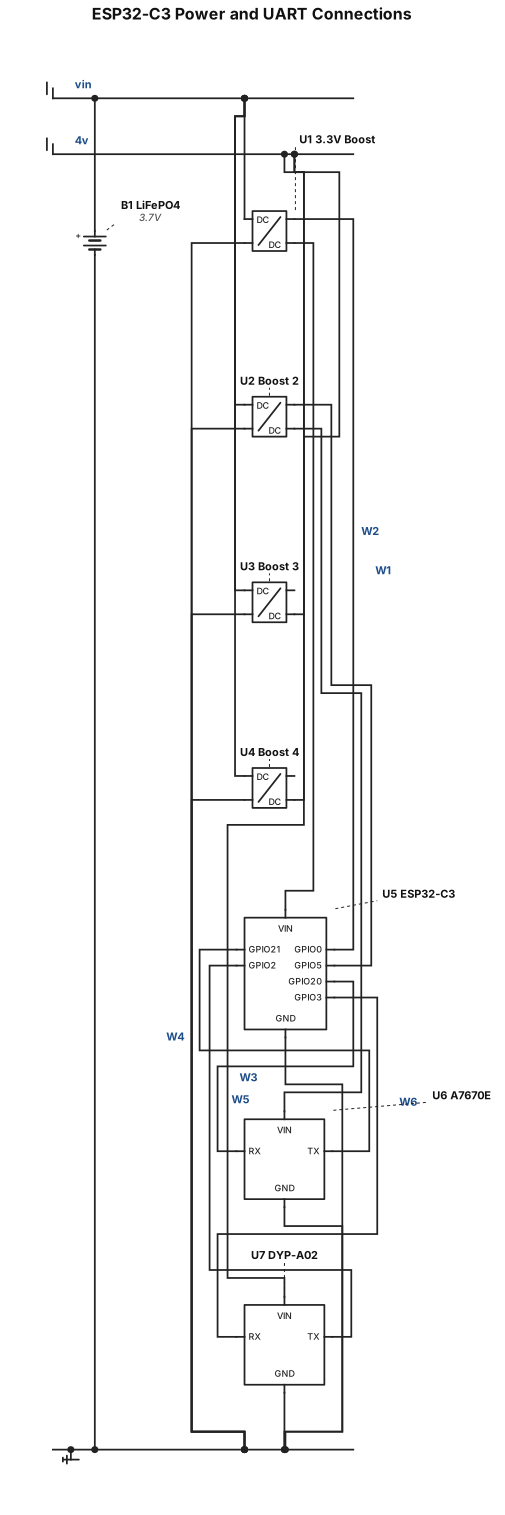
Power & Supply * LiFePO4 Battery (+) \rightarrow VIN of 3.3V Boost Converter & VIN of 3 boost converters * Common Ground \rightarrow Shared across all components (ESP32-C3, battery, boost converters, A7670E, DYP-A02) * Boost Converter Enable (EN) Pins * ESP32-C3 GPIO 0 \rightarrow Booster 1 EN * ESP32-C3 GPIO 5 \rightarrow Booster 2 EN * A7670E Cellular Module (UART) * ESP32-C3 GPIO 20 \rightarrow A7670E RX * ESP32-C3 GPIO 21 \rightarrow A7670E TX * DYP-A02 Sensor (UART) * ESP32-C3 GPIO 2 \rightarrow DYP-A02 TX * ESP32-C3 GPIO 3 \rightarrow DYP-A02 RX
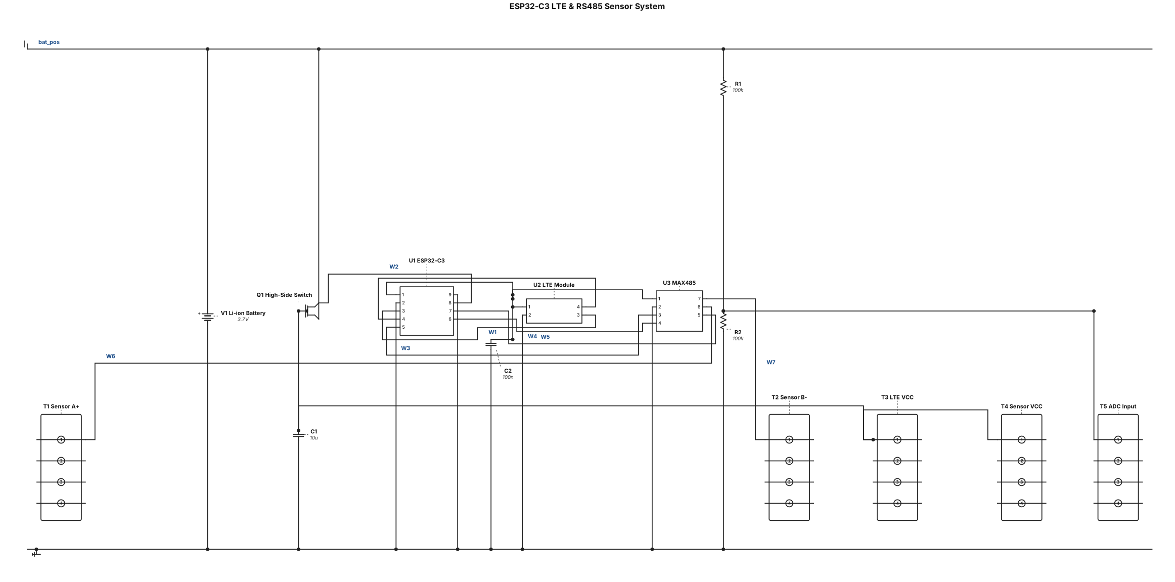
ESP32-C3 Pinout & Wiring Connections LTE Module (UART) ESP32 GPIO 21 (TX) \rightarrow LTE Module RX ESP32 GPIO 20 (RX) \rightarrow LTE Module TX Area-Velocity Sensor via RS485 Transceiver (MAX485) ESP32 GPIO 4 (TX) \rightarrow MAX485 DI (Driver Input) ESP32 GPIO 5 (RX) \rightarrow MAX485 RO (Receiver Output) ESP32 GPIO 6 \rightarrow MAX485 DE / RE (Data Enable / Receive Enable) MAX485 A \rightarrow Sensor RS485 A (+) MAX485 B \rightarrow Sensor RS485 B (-) Power Switching (MOSFET Control) ESP32 GPIO 3 \rightarrow MOSFET Gate (Controls high-side power switch for LTE & Sensor VCC) Battery Voltage Monitor (ADC) ESP32 GPIO 0 (ADC1_CH0) \rightarrow Resistor Voltage Divider midpoint (Connected to Battery V+) Power & Ground Rails ESP32 3V3 \rightarrow Regulated 3.3V DC Output (from DC-DC Buck Converter) ESP32 GND \rightarrow Common System Ground (Shared with Battery Negative, DC-DC GND, LTE GND, and Sensor GND)
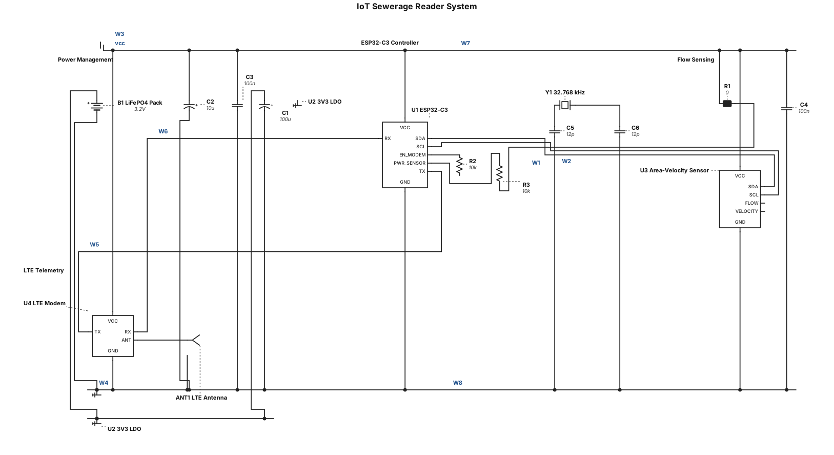
Generate a comprehensive technical system architecture and data-flow diagram for an IoT sewerage reader device. The system features an ESP32-C3 microcontroller powered by a LiFePO4 battery pack, connected to an area-velocity flow sensor and an LTE telemetry module. Include a duty-cycle state machine that wakes from deep sleep, polls sensors, evaluates blockage/flow thresholds, powers up the cellular modem to transmit data, and returns to deep sleep.
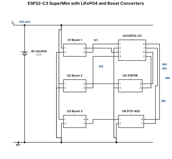
ESP32 C3 SuperMini powered from a 3.2V LiFePO4 battery through a 3.3V boost converter. Battery positive connects to the VIN of three boost converters. GPIO 0 controls Booster 1 EN, GPIO 5 controls Booster 2 EN, GPIO 20 connects directly to A7670E RX, GPIO 21 connects directly to A7670E TX, GPIO 2 connects to DYP-A02 TX, GPIO 3 connects to DYP-A02 RX. All components share a common ground.
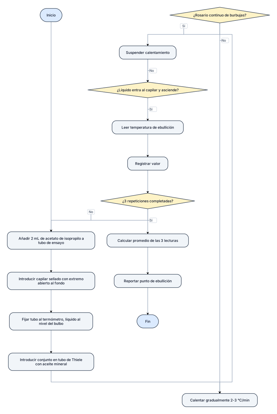
Diagarma de flujo para: el punto de ebullición A un tubo de ensayo pequeño se añaden 2 mL de acetato de isopropilo, se introduce un capilar sellado por uno de sus extremos de modo que el extremo abierto toque el fondo del tubo y luego se fija al termómetro procurando que la columna del líquido quede al nivel del bulbo del termómetro. El conjunto se introduce en el tubo de Thiele con aceite mineral y se empieza el calentamiento. Se calienta gradualmente (2-3 °C/min) hasta que del capilar se desprenda un rosario continuo de burbujas. En seguida se suspende el calentamiento y en el instante en que el líquido entre por el capilar y empiece a ascender se lee la temperatura de ebullición.[7] haga con 3 repeticiones .Determine el punto de ebullición
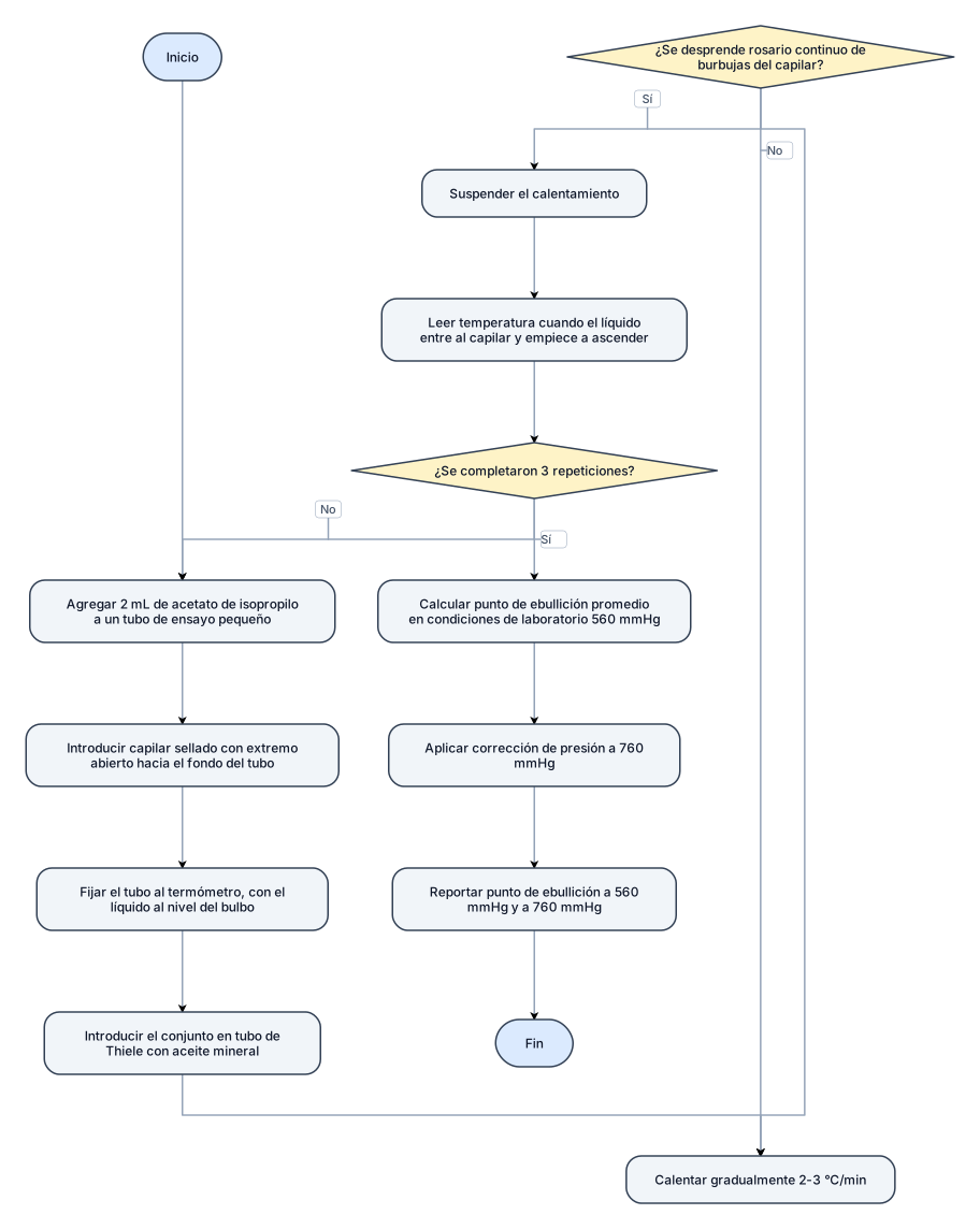
Diagarma de flujo para: el punto de ebullición A un tubo de ensayo pequeño se añaden 2 mL de acetato de isopropilo, se introduce un capilar sellado por uno de sus extremos de modo que el extremo abierto toque el fondo del tubo y luego se fija al termómetro procurando que la columna del líquido quede al nivel del bulbo del termómetro. El conjunto se introduce en el tubo de Thiele con aceite mineral y se empieza el calentamiento. Se calienta gradualmente (2-3 °C/min) hasta que del capilar se desprenda un rosario continuo de burbujas. En seguida se suspende el calentamiento y en el instante en que el líquido entre por el capilar y empiece a ascender se lee la temperatura de ebullición.[7] Determine el punto de ebullición en condiciones del laboratorio para el acetato de isopropilo con 3 repeticiones. reporte el punto de ebullición a condiciones de laboratorio (560 mmHg) y a condiciones estándar (760 mmHg) con las respectivas correcciones
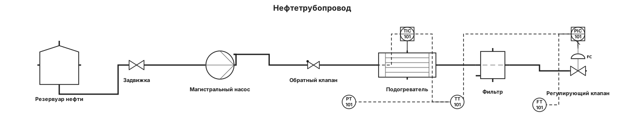
P&ID для нефтетрубопровода. Схема по госту
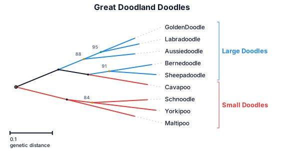
A phylogenetic tree of the great doodland doodles
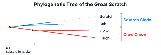
A phylogenetic tree of the great scratch
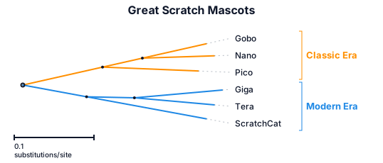
A phylogenetic tree of the great scratch mascots
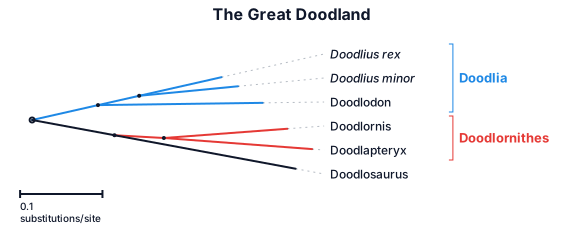
A phylogenetic tree of the great Doodland
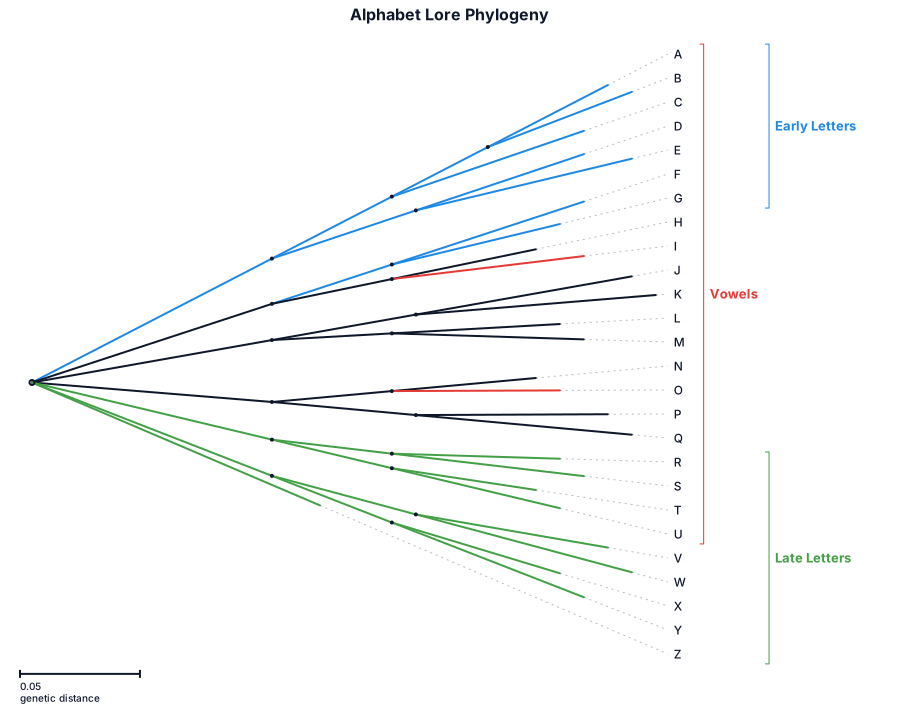
A phylogenetic tree of the great Alphabet lore
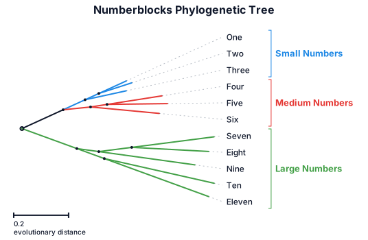
A phylogenetic tree of the great numberblocks
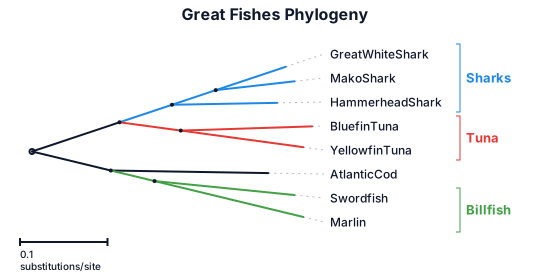
A phylogenetic tree of the great fishes
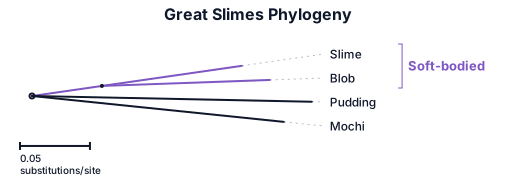
A phylogenetic tree of the great slimes: slime blob pudding and mochis
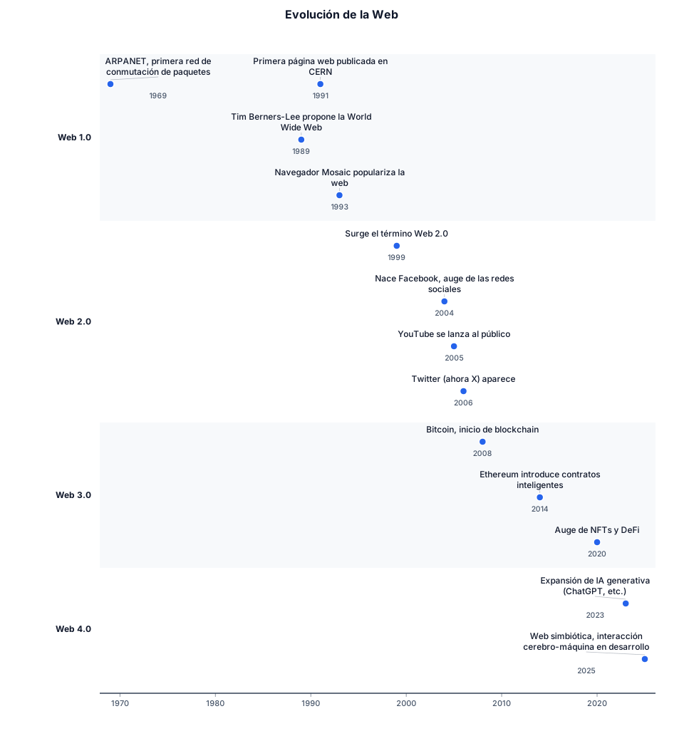
LINEA DE TIEMPO HACERCA DEL INTERNET EVOLUCION DE LA WEB
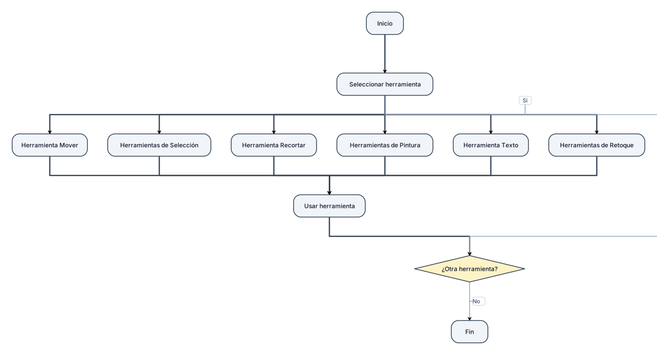
Un diagrama de flujo sobre las herramientas de photoshop
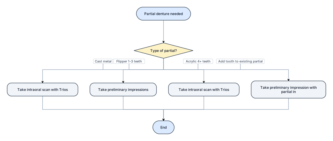
Partial denture process: for cast metal process, take intraoral scan with Trios. For flipper replacing 1-3 teeth, take preliminary impressions. For acrylic partial denture replacing 4+ teeth, take intraoral scan with Trios. for adding tooth to existing partial, take preliminary impression with partial in