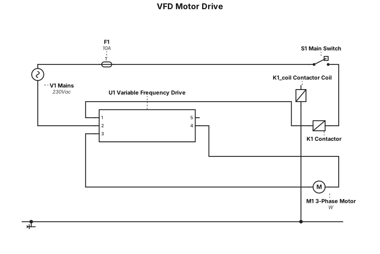
a vfd circuit
NODE ARCHIVE · REAL DIAGRAM BRIEFS
Diagram Examples from Real Visitor Prompts
Browse eligible diagrams shared by FreeDiagram visitors, inspect the exact prompts, and build your own version.
Browse 3263 real creationsCOMMUNITY OUTPUTS · EXACT PROMPTS
All visitor creations
Showing 241–264 of 3263. No stock examples or system defaults. Choose a tool, study a real result, then reopen its prompt as your starting point.
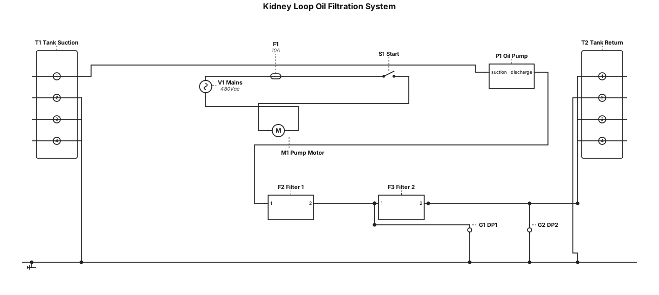
A kidney loop oil filteration sysytem with two particulate filter
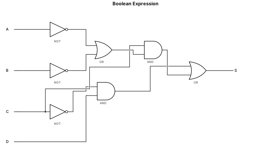
\mathrm{S}=\bar{\mathrm{C}}\mathrm{D}+\mathrm{C}\bar{\mathrm{D}}\ (\bar{\mathrm{A}}+\bar{\mathrm{B}})
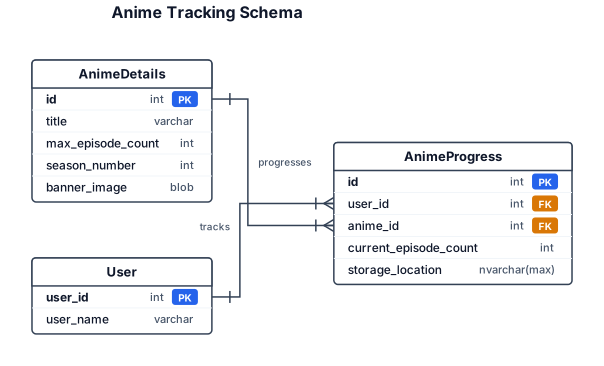
An ER diagram for tracking anime details and individual user lists for their progress. There should be an Anime Details table that has an id as a primary key. It also has title, max episode count, season number, and a banner image stored as a blob. The Anime progress table has an id for the PK and a user id as a FK. It also has the anime id as a FK and the current episode count and a storage location as a nvarchar max. The user table just has a user id and a user name.
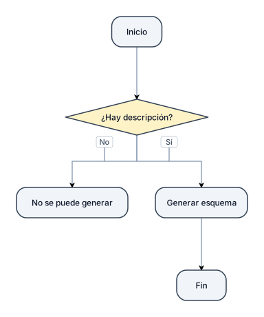
Genera este esquema
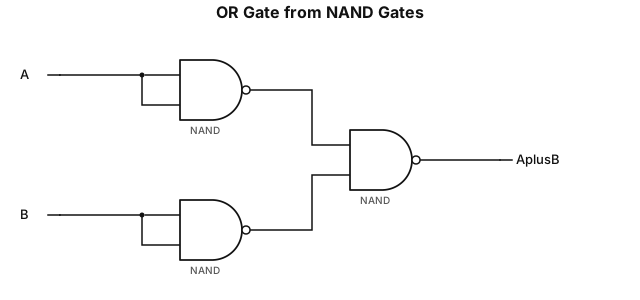
OR Gate Implementation:Show two inputs, $A$ and $B$.Feed input $A$ into a NAND-based NOT gate to get $\overline{A}$, and input $B$ into another NAND-based NOT gate to get $\overline{B}$.Feed both $\overline{A}$ and $\overline{B}$ into a third NAND gate.Label the final output as $A + B$.
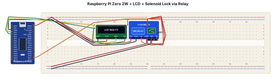
i need a wiring diagram for a breadboard containing a raspberry pi zero 2w, lcd screen and a solenoid lock with digital relay. These are being powered by 12v mains plug
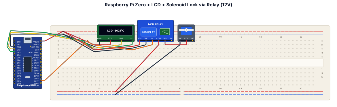
i need a wiring diagram for a breadboard containing a raspberry pi zero, lcd screen and a solenoid lock with digital relay. These are being powered by 12v mains plug
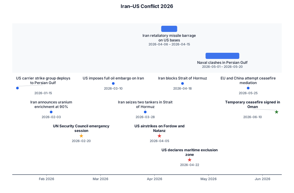
iran-us war in 2026
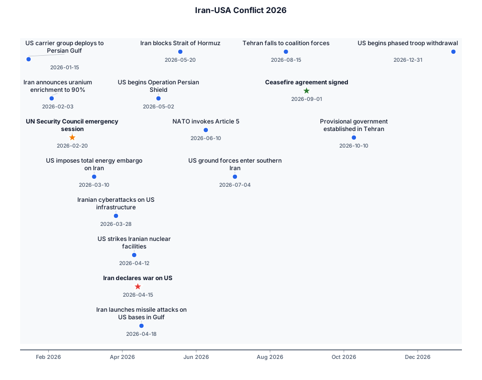
iran-usa war in 2026
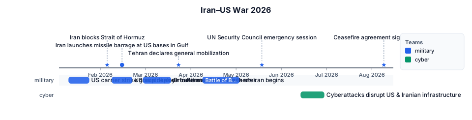
iran and use war 2026
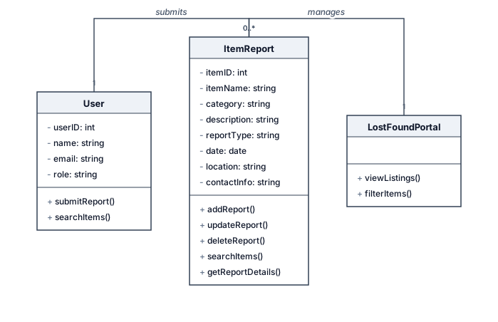
Create a UML Class Diagram for a simple academic project named College Lost and Found Portal. The website allows students and college staff to submit lost-item reports, submit found-item reports, view listings, and search or filter items. Use a simple design with only the necessary classes. ItemReport: * itemID: integer (primary key) * itemName: string * category: string * description: string * reportType: string (Lost or Found) * date: date * location: string * contactInfo: string Operations: * addReport() * updateReport() * deleteReport() * searchItems() * getReportDetails() Do not add login, payment, notifications, or other unplanned features. Keep the diagram readable and suitable for a college project report.
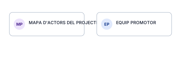
Create a clean, professional 16:9 organizational infographic for a public-sector HR management project. Use a white background, navy blue and teal accents, simple icons, readable typography, and five numbered sections arranged in a balanced layout. All visible text must remain in Catalan. Preserve the exact wording of the supplied labels. Do not translate, invent, or modify any roles. Title: MAPA D'ACTORS DEL PROJECTE EQUIP PROMOTOR Direcció General / Regidoria Responsable de Recursos Humans — Cap de Nòmines i Prestacions RESPONSABLES DEL PROJECTE Cap de Projecte de RH — Cap de Nòmines i Prestacions Cap de Projecte d'IT — Cap de Servei de Població ALTRES SERVEIS Contractació Gestió Econòmica / Comptabilitat Assessoria Jurídica Delegat/da de Protecció de Dades ACTOR EXTERN Empresa adjudicatària USUARIS Usuaris de gestió: responsables de RH i comandaments intermedis. Usuaris finals: tota la plantilla, mitjançant el Portal de l'Empleat. Show the five sections as distinct visual groups. Prioritize clarity, hierarchy, and legibility. Do not invent reporting lines. Create a polished institutional infographic suitable for a formal presentation.
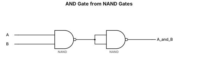
AND Gate Implementation:Show a 2-input NAND gate with inputs $A$ and $B$, producing an intermediate output $\overline{A \cdot B}$.Connect this output into a second NAND gate configured as a NOT gate (both inputs tied together).Label the final output as $A \cdot B$.
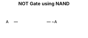
NOT Gate Implementation:Show a single 2-input NAND gate where both inputs ($A$) are tied together into a single input line.Label the input as $A$ and the output as $\overline{A}$.
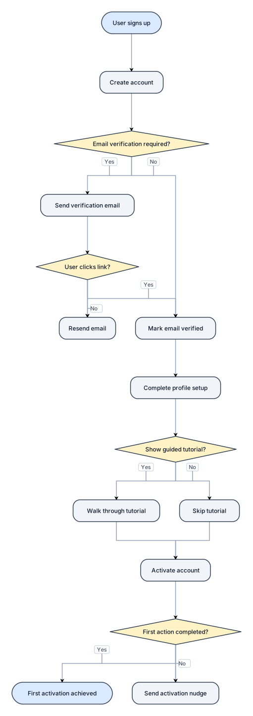
A flowchart of a new-user onboarding flow from signup to first activation, with a verification branch
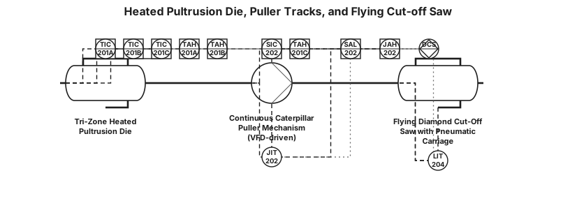
Generate an ANSI/ISA-5.1-2024 P&ID diagram for Heated Pultrusion Die, Puller Tracks, and Flying Cut-off Saw. EQUIPMENT: - EQ-DAD-201: Tri-Zone Heated Pultrusion Die. - EQ-PUL-201: Continuous Caterpillar Puller Mechanism (VFD-driven). - EQ-SAW-202: Flying Diamond Cut-Off Saw with Pneumatic Carriage. INSTRUMENTATION & CLOSED LOOPS: - LOOP 201 (Die Thermal Profile): * TIC-201A: Zone 1 Preheating Temp Controller (Setpoint: 100.0 °C, Alarm TAH-201A > 120 °C). * TIC-201B: Zone 2 Gelation Temp Controller (Setpoint: 130.0 °C, Alarm TAH-201B > 150 °C). * TIC-201C: Zone 3 Final Curing Temp Controller (Setpoint: 150.0 °C, Alarm TAH-201C > 170 °C). - LOOP 202 (Pulling Speed & Load): * SIC-202: VFD Speed Controller for EQ-PUL-201 (Setpoint: 0.30 m/min, Low Alarm SAL-202 < 0.15 m/min). * JIT-202: Pulling Force Load Cell Transmitter (Nominal: 4.5 kN, Jamming Alarm JAH-202 > 12.0 kN). - SAW CONTROL: * LIT-204: Optical Length Sensor on EQ-SAW-202 (Setpoint: L = 180.0 mm ± 0.2 mm). SAFETY INTERLOCKS: - Interlock [I-201]: Red dashed line from JIT-202 (JAH-202 > 12 kN trigger) to Safety Logic [I-201], sending trip signal to immediately stop SIC-202 puller motor. - Interlock [I-202]: Red dashed line from LIT-204 length sensor to [I-202] to synchronize saw carriage pneumatic movement with continuous profile speed. CONNECTIONS: - Main Process Line (thick black): Impregnated composite profile through EQ-DAD-201 -> EQ-PUL-201 -> EQ-SAW-202. - Electrical Signals (dashed): All TIC, SIC, JIT, LIT sensors to DCS.
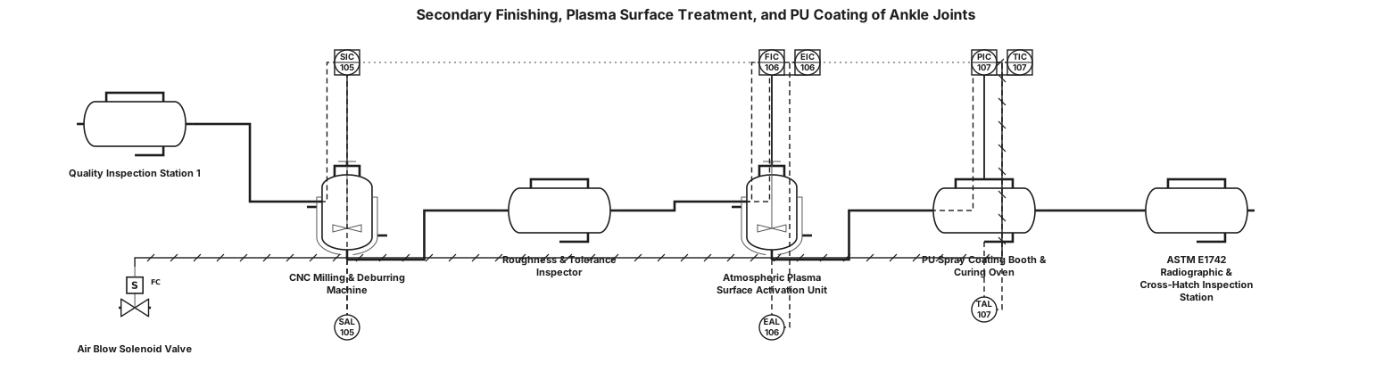
Generate an ANSI/ISA-5.1-2024 P&ID diagram for Secondary Finishing, Plasma Surface Treatment, and PU Coating of Ankle Joints. EQUIPMENT: - EQ-QC-101: Quality Inspection Station 1 (Dimensional & Sink marks). - EQ-CNC-101: CNC Milling & Deburring Machine for pivots. - FCV-105: Air Blow Solenoid Valve. - EQ-QC-102: Roughness (Ra < 1.6 µm) and Tolerance Inspector. - EQ-PLS-101: Atmospheric Plasma Surface Activation Unit. - EQ-COAT-101: PU Spray Coating Booth & Curing Oven (60.0 °C). - EQ-NDT-101: ASTM E1742 Radiographic & Cross-Hatch Inspection Station. INSTRUMENTATION & CONTROL LOOPS: - SIC-105: CNC Spindle Speed Controller on EQ-CNC-101 (Setpoint: 3,500 RPM, Low Alarm SAL-105 < 3,000 RPM). - FIC-106 & EIC-106: Plasma Gas Flow & Power Controller on EQ-PLS-101 (Setpoint > 48 mN/m surface energy, Alarm EAL-106 < 48 mN/m). - PIC-107: Spray Pressure Controller on EQ-COAT-101 (Setpoint: 2.5 bar, Pneumatic line). - TIC-107: Curing Oven Temp Controller on EQ-COAT-101 (Setpoint: 60.0 °C, Low Alarm TAL-107 < 55.0 °C). CONNECTIONS: - Main Process Line (thick solid line): Part transportation sequence EQ-QC-101 -> EQ-CNC-101 -> EQ-QC-102 -> EQ-PLS-101 -> EQ-COAT-101 -> EQ-NDT-101. - Pneumatic Signal Line (double slashed / dashed): PIC-107 to Spray Nozzle and FCV-105 air supply. - Digital Signals (dashed): SIC-105, EIC-106, TIC-107 to Central PLC.

Generate an ANSI/ISA-5.1-2024 P&ID diagram for Secondary Drilling, Edge Sealing, Coating, and Mechanical NDT of Composite Holders. EQUIPMENT: - EQ-QC-201: Barcol Hardness Inspection Station (> 45 Barcol). - EQ-DRILL-202: CNC Drilling Machine with Brad-Point Carbide Drill and Sacrificial Backing Plate. - EQ-QC-202: 10x Optical Inspection Station for Delamination. - EQ-SEAL-202: Epoxy Edge Sealer Applicator & Curing Oven (80.0 °C, 15 min). - EQ-COAT-202: Topcoat PU Application & Thickness Monitor. - EQ-NDT-202: ISO 10328 Proof Load Testing Machine (P5 = 2,688 N) + ASTM D570 Gravimetric Test. INSTRUMENTATION & CONTROL LOOPS: - SIC-205: Drill Spindle Speed Controller (Setpoint: 3,200 RPM, Alarm SAL-205 < 2,800 RPM). - FIC-205: Drill Feed Rate Servo Controller (Setpoint: 0.04 mm/rev, High Alarm FAH-205 > 0.08 mm/rev). - TIC-206: Epoxy Curing Oven Temp Controller on EQ-SEAL-202 (Setpoint: 80.0 °C, Low Alarm TAL-206 < 70.0 °C). - AIT-207: In-line Optical PU Film Thickness Analyzer on EQ-COAT-202 (Setpoint: 40 µm, Range: 30 - 50 µm, Low Alarm AAL-207 < 30 µm). CONNECTIONS: - Main Process Line (thick black): Part travel sequence EQ-QC-201 -> EQ-DRILL-202 -> EQ-QC-202 -> EQ-SEAL-202 -> EQ-COAT-202 -> EQ-NDT-202. - Electrical Signal Lines (dashed): SIC-205, FIC-205, TIC-206, AIT-207 to DCS/PLC.
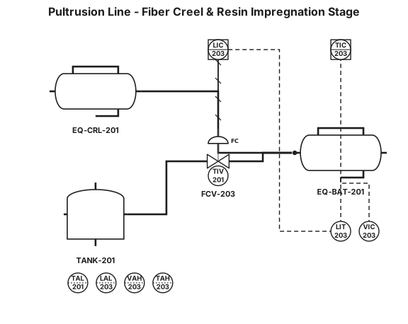
Generate an ANSI/ISA-5.1-2024 P&ID diagram for Fiber Creel and Resin Impregnation Stage of a Pultrusion Line. EQUIPMENT: - EQ-CRL-201: Unidirectional Glass Fiber Creel (E-Glass Rovings 0°). - EQ-BAT-201: Unsaturated Polyester Resin Impregnation Bath with Jacket Control. - FCV-203: Resin Supply Control Valve (Fail Closed - FC). INSTRUMENTATION & CLOSED LOOPS (LOOP 203): - TIV-201: Mechanical Tension Indicator/Control Valve on EQ-CRL-201 (Setpoint: 15.0 N, Low Alarm TAL-201 < 5 N). - LIT-203: Capacitive Resin Level Transmitter in EQ-BAT-201 (Setpoint: 30 cm, Low Alarm LAL-203 < 10 cm, controlling FCV-203). - VIC-203: In-line Rotational Viscometer (Setpoint: 0.30 - 0.60 Pa·s / 450 cP at 23 °C, High Alarm VAH-203 > 0.60 Pa·s). - TIC-203: Bath Temperature Controller (Setpoint: 23.0 °C, High Temp Alarm TAH-203 > 28.0 °C). CONNECTIONS: - Main Process Line (thick black): Glass Fiber Roving path from EQ-CRL-201 through EQ-BAT-201 resin bath to die inlet. - Fluid Feed Line: Resin supply tank through FCV-203 into EQ-BAT-201. - Electrical Signal Lines (dashed): LIT-203, VIC-203, TIC-203 to DCS/PLC.
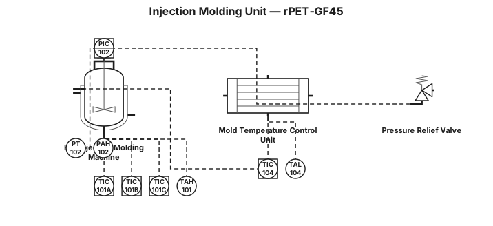
Generate an ANSI/ISA-5.1-2024 P&ID diagram for an Injection Molding Unit for rPET-GF45. EQUIPMENT: - EQ-INJ-101: Hot Injection Molding Machine with Screw Barrel and Nozzle. - PSV-102: Pressure Relief Safety Valve on Hydraulic Line (Fail Open - FO). - EQ-TCU-101: Mold Temperature Control Unit (120.0 °C). INSTRUMENTATION & CLOSED LOOPS: - LOOP 101 (Tri-Zone Thermal Profile): * TIC-101A: Temp Controller Zone 1 Feed (Setpoint: 270.0 °C, RTD Pt100). * TIC-101B: Temp Controller Zone 2 Plastification (Setpoint: 285.0 °C, RTD Pt100). * TIC-101C: Temp Controller Zone 3 Nozzle (Setpoint: 285.0 °C, RTD Pt100). * High Temp Alarm TAH-101 > 300.0 °C. - LOOP 102 (Holding Pressure): * PT-102: Piezoelectric Pressure Transducer in Cavity/Nozzle. * PIC-102: PID Pressure Controller (Setpoint: 80.0 MPa / 120 bar hydraulic, High Alarm PAH-102 > 140 bar). - LOOP 104 (Mold Crystallization Control): * TIC-104: TCU Temp Controller (Setpoint: 120.0 °C, Low Temp Alarm TAL-104 < 110.0 °C). SAFETY INTERLOCKS: - Interlock [I-101B]: Red dashed line from PIC-102 (PAH-102 trigger) to [I-101B], sending trip signal to de-energize EQ-INJ-101 screw motor and open PSV-102 (FO). - Interlock [I-101C]: Red dashed line from TIC-104 (TAL-104 trigger) to [I-101C], sending interlock signal to block injection trigger. CONNECTIONS: - Main Process Line (thick black): Polymer melt flow to Mold. - Thermal fluid loop (thick line): EQ-TCU-101 to Mold cooling channels. - Electrical signals (dashed): All TIC, PT, PIC to DCS/PLC.
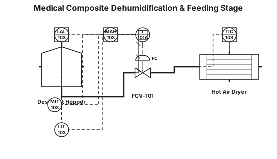
Generate a clean, high-precision ANSI/ISA-5.1-2024 P&ID diagram for a Medical Composite Dehumidification & Feeding Stage. EQUIPMENT: - EQ-HOP-101: Desiccant Hopper (DCS-connected). - EQ-DRY-101: Hot Air Dryer (120.0 °C). - FCV-101: Feeding Control Valve (Fail Closed - FC). INSTRUMENTATION & CLOSED LOOPS (LOOP 103): - LIT-103: Ultrasonic Level Transmitter on EQ-HOP-101 (Setpoint: 80%, Low Alarm LAL-103 < 20%). - TIC-103: PID Dryer Temp Controller for EQ-DRY-101 (Setpoint: 120.0 °C, RTD Pt100). - MIT-103: Moisture Transmitter ISO 15512 in pellets (Setpoint <= 200 ppm, High Moisture Alarm MAH-103 > 200 ppm). SAFETY INTERLOCK (I-101A): - Draw a red dashed safety interlock line from MIT-103 (MAH-103 trigger) to Safety Logic Box [I-101A]. - Connect [I-101A] via red dashed line to close FCV-101 (FC) and disable barrel feeding upon high moisture. CONNECTIONS: - Main Process Line (thick solid black): Granule feed to EQ-HOP-101, through FCV-101 to EQ-DRY-101, discharging to Injection Barrel inlet. - Electrical/DCS Signal (dashed line): LIT-103, TIC-103, MIT-103 to DCS/PLC. - Include ISA legend for line types and FC valve position.
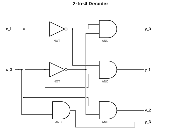
Task: Draw a circuit diagram of a 2-to-4 decoder based on a network of logic gates. Operation and logic: Inputs: x_1 and x_0 (a 2-bit binary number). Outputs: y_3, y_2, y_1, y_0 (one-hot encoding). Boolean equations: y_0 = \bar{x}_1 \bar{x}_0, y_1 = \bar{x}_1 x_0, y_2 = x_1 \bar{x}_0, y_3 = x_1 x_0. Diagram construction instructions: Place two input lines, x_1 and x_0, on the left side. Add NOT gates (inverters) to the input lines to obtain the negated signals \bar{x}_1 and \bar{x}_0. On the right side, place four 2-input AND gates (or AND gates with inverted inputs—indicated by "bubbles"). Connect the inputs to the AND gates as follows: First AND gate: inputs \bar{x}_1 and \bar{x}_0 \rightarrow output y_0. Second AND gate: inputs \bar{x}_1 and x_0 \rightarrow output y_1. Third AND gate: inputs x_1 and \bar{x}_0 \rightarrow output y_2. Fourth AND gate: inputs x_1 and x_0 \rightarrow output y_3. Label the inputs of all gates and... outputs clearly labeled (x_1, x_0, y_0, y_1, y_2, y_3). Draw the diagram with a clear white background and black lines. and can you make the x stand sidebyside and the y stand sidebyside
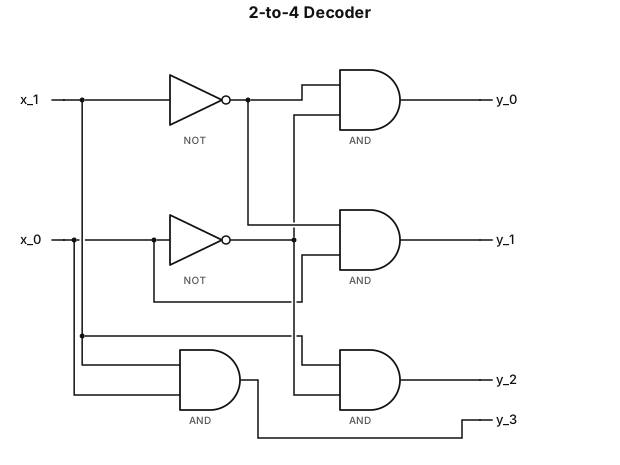
Task: Draw a circuit diagram of a 2-to-4 decoder based on a network of logic gates. Operation and logic: Inputs: x_1 and x_0 (a 2-bit binary number). Outputs: y_3, y_2, y_1, y_0 (one-hot encoding). Boolean equations: y_0 = \bar{x}_1 \bar{x}_0, y_1 = \bar{x}_1 x_0, y_2 = x_1 \bar{x}_0, y_3 = x_1 x_0. Diagram construction instructions: Place two input lines, x_1 and x_0, on the left side. Add NOT gates (inverters) to the input lines to obtain the negated signals \bar{x}_1 and \bar{x}_0. On the right side, place four 2-input AND gates (or AND gates with inverted inputs—indicated by "bubbles"). Connect the inputs to the AND gates as follows: First AND gate: inputs \bar{x}_1 and \bar{x}_0 \rightarrow output y_0. Second AND gate: inputs \bar{x}_1 and x_0 \rightarrow output y_1. Third AND gate: inputs x_1 and \bar{x}_0 \rightarrow output y_2. Fourth AND gate: inputs x_1 and x_0 \rightarrow output y_3. Label the inputs of all gates and... outputs clearly labeled (x_1, x_0, y_0, y_1, y_2, y_3). Draw the diagram with a clear white background and black lines.