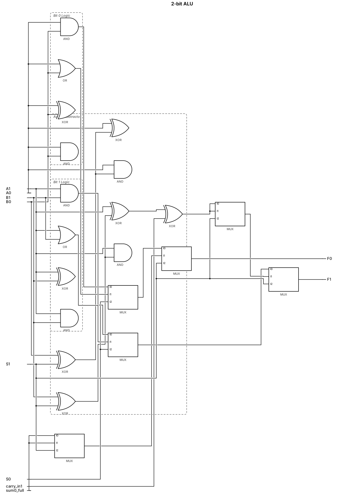
2.5 Design and Implementation of a 2-bit ALU Inputs: A = A1A0 and B = B1B0 S1 S0 Operation 0 0 A AND B 0 1 A OR B 1 0 A + B 1 1 A − B Design The ALU is designed to select one of four operations using 2×1 multiplexers and basic logic gates. The arithmetic operations use the required adder/subtractor logic.
NODE ARCHIVE · REAL DIAGRAM BRIEFS
Diagram Examples from Real Visitor Prompts
Browse eligible diagrams shared by FreeDiagram visitors, inspect the exact prompts, and build your own version.
Browse 3265 real creationsCOMMUNITY OUTPUTS · EXACT PROMPTS
All visitor creations
Showing 289–312 of 3265. No stock examples or system defaults. Choose a tool, study a real result, then reopen its prompt as your starting point.
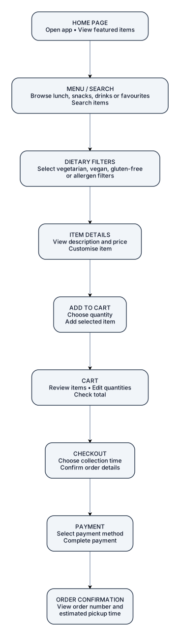
now this Map out a linear User Flow diagram using connecting arrows to show step-by-step screen navigation. 1. HOME PAGE Open app • View featured items 2. MENU / SEARCH Browse lunch, snacks, drinks or favourites • Search items 3. DIETARY FILTERS Select vegetarian, vegan, gluten-free or allergen filters 4. ITEM DETAILS View description and price • Customise item 5. ADD TO CART Choose quantity • Add selected item 6. CART Review items • Edit quantities • Check total 7. CHECKOUT Choose collection time • Confirm order details 8. PAYMENT Select payment method • Complete payment 9. ORDER CONFIRMATION View order number and estimated pickup time CAN U MAKE IT IN PORTRAIT FORM

now this Map out a linear User Flow diagram using connecting arrows to show step-by-step screen navigation. 1. HOME PAGE Open app • View featured items 2. MENU / SEARCH Browse lunch, snacks, drinks or favourites • Search items 3. DIETARY FILTERS Select vegetarian, vegan, gluten-free or allergen filters 4. ITEM DETAILS View description and price • Customise item 5. ADD TO CART Choose quantity • Add selected item 6. CART Review items • Edit quantities • Check total 7. CHECKOUT Choose collection time • Confirm order details 8. PAYMENT Select payment method • Complete payment 9. ORDER CONFIRMATION View order number and estimated pickup time
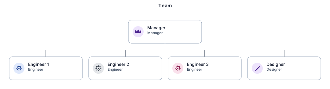
An org chart for a small team with a manager, three engineers, and a designer
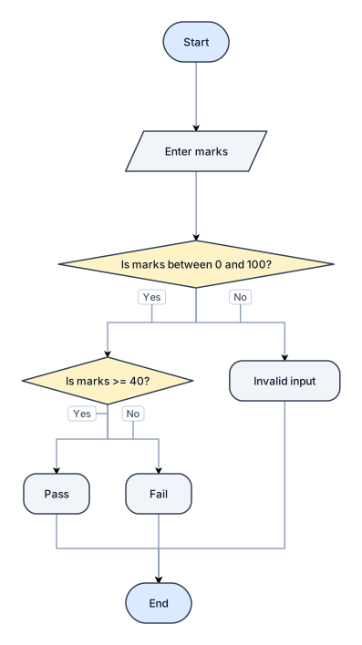
Create a flowchart for a student result system. Take marks as input, check whether marks are between 0 and 100, then determine Pass if marks are 40 or above and Fail otherwise. Include input validation, decision branches, output and Start/End symbols.
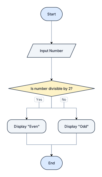
Create a flowchart to check whether a number entered by the user is even or odd. Include Start, Input Number, a decision diamond to check if the number is divisible by 2, Yes and No branches, display the result, and End. Use standard flowchart symbols and label all arrows clearly.
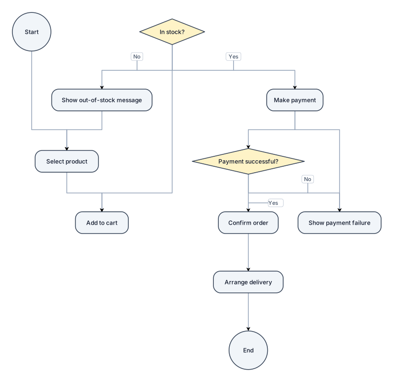
Generate a flowchart for an online shopping system, from selecting a product to adding it to the cart, checking stock, making payment, confirming the order, and arranging delivery. Include branches for out-of-stock products and failed payments.
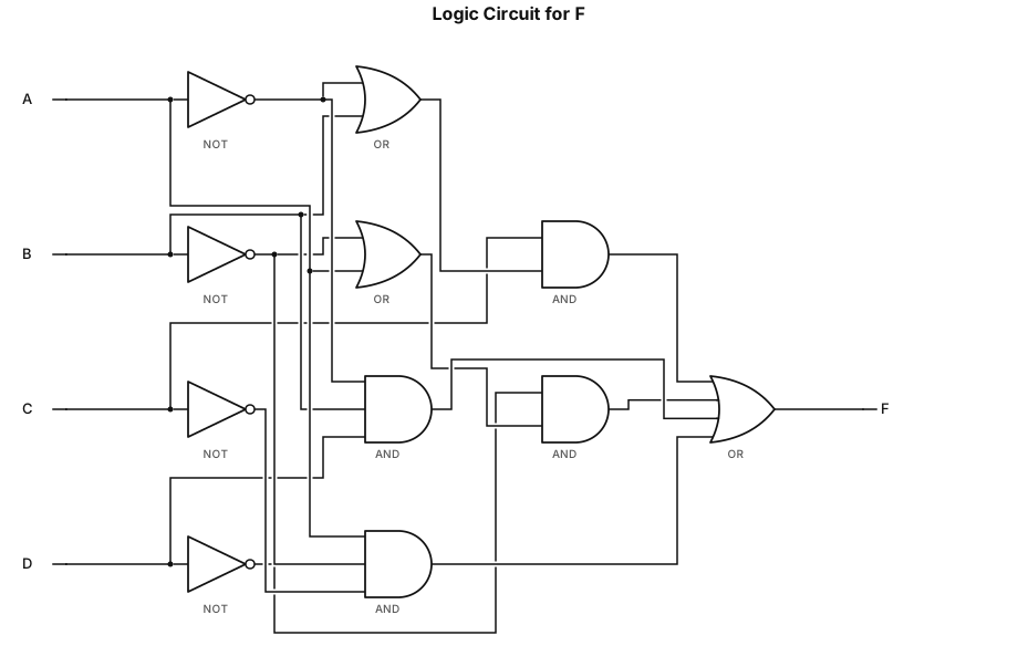
Draw the logic circuit diagram for F = C(A'+B)+D'(B'+A)+A'BD+AB'C'
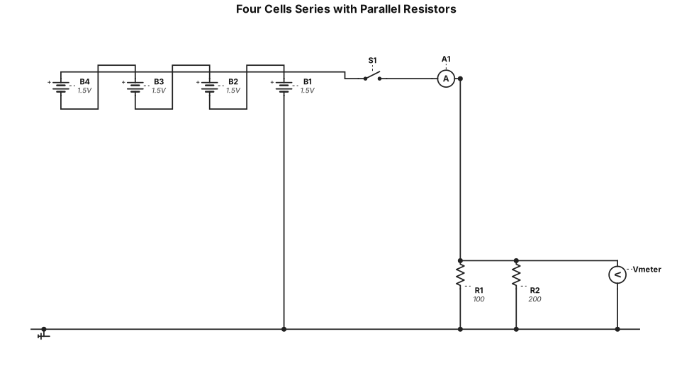
four cells in serie, two resistors in parallel, closed switch, ammeter in main stream and a VOLTMETER over second resistor
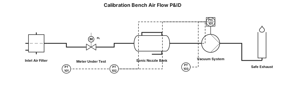
The P&ID shows how air enters the calibration bench, passes through the meter under test, is referenced by the sonic-nozzle bank, and is finally drawn through the vacuum system to safe exhaust.”

A P&ID for a Gas metering and calibration unit where atmospheric air passes the inlet isolation valve and filter, where differential pressure is monitored. It then passes through the straight-run flow conditioner and into the UUT test section. This is where the customer’s meter is installed and secured. Reference — Downstream, the flow reaches the upstream plenum and the 20-nozzle critical-flow bank. The selected calibrated nozzle or nozzle combination establishes the reference flow under controlled pressure and temperature conditions. This is the metrology heart of the system. Vacuum & exhaust — The reference flow then enters the vacuum manifold. The P&ID provides low-flow and high-flow suction branches with blower, non-return and isolation protection. The discharge is routed through the silencer to the safe exhaust. Controls & safety — The PLC/HMI supervises the sequence, measurements and permissives. The design includes pressure, temperature, vibration and other monitoring, together with clamp/interlock and safe shutdown functions. A calibration result should only be accepted when the reference and test conditions are valid and stable. Close — In summary, the P&ID provides the complete calibration architecture: controlled inlet, protected UUT, traceable sonic-nozzle reference, selectable suction, monitored operation and safe exhaust. The next step is to close detailed engineering items before construction release.
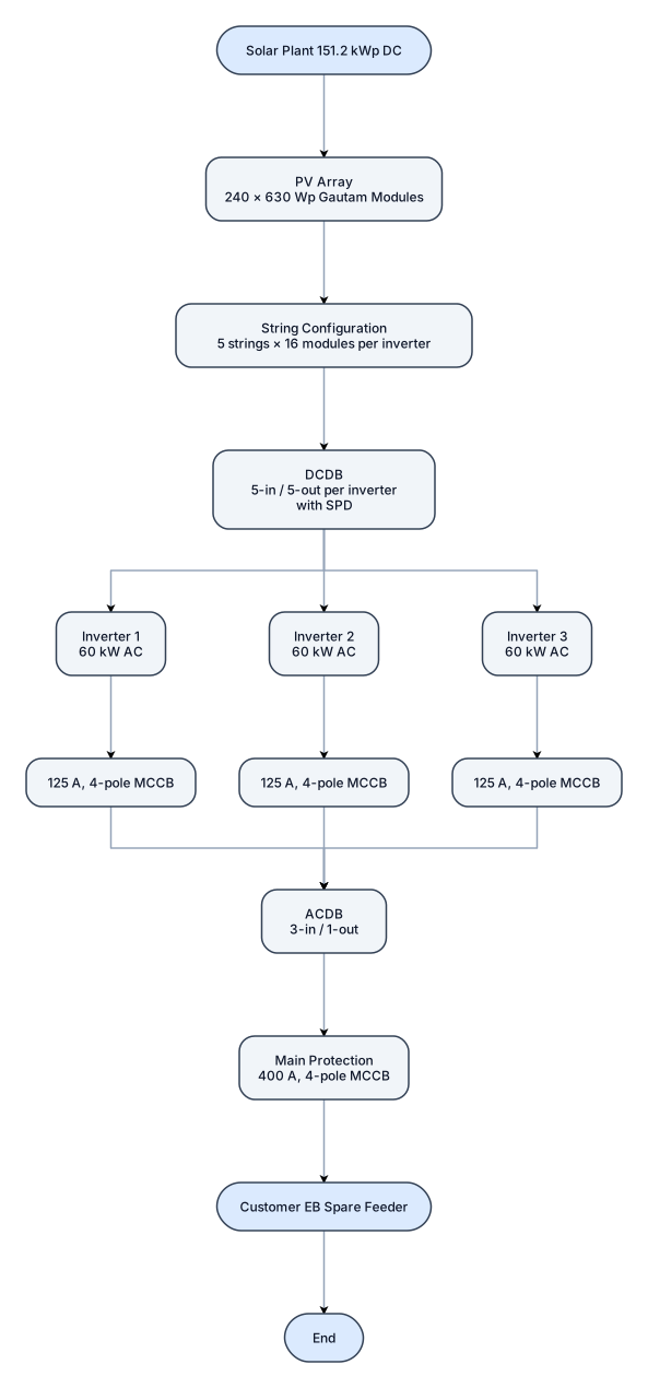
A flowchart for solaR PLANT PV capacity: 151.2 kWp DC Inverter capacity: 3 × 60 kW = 180 kW AC - make evvo PV modules: 240 × 630 Wp Gautam String configuration: 5 strings × 16 modules per inverter DCDB: 5-in / 5-out per inverter with spd ACDB: 3-in / 1-out Main protection: 400 A, 4-pole MCCB Inverter protection: 125 A, 4-pole MCCB per inverter Output: Customer EB spare feede
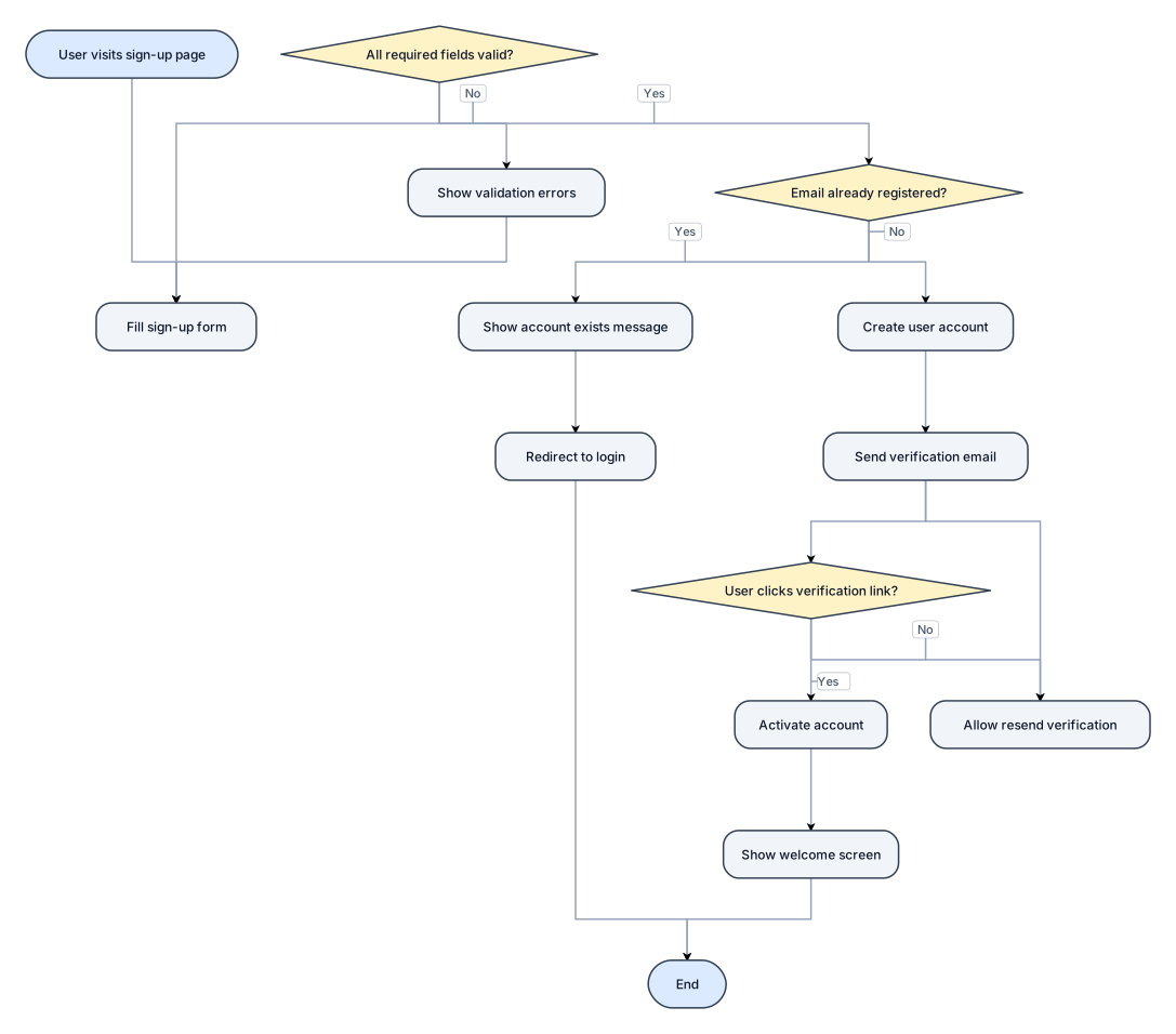
A flowchart for a user sign-up process: PV capacity: 151.2 kWp DC Inverter capacity: 3 × 60 kW = 180 kW AC - make evvo PV modules: 240 × 630 Wp Gautam String configuration: 5 strings × 16 modules per inverter DCDB: 5-in / 5-out per inverter with spd ACDB: 3-in / 1-out Main protection: 400 A, 4-pole MCCB Inverter protection: 125 A, 4-pole MCCB per inverter Output: Customer EB spare feede
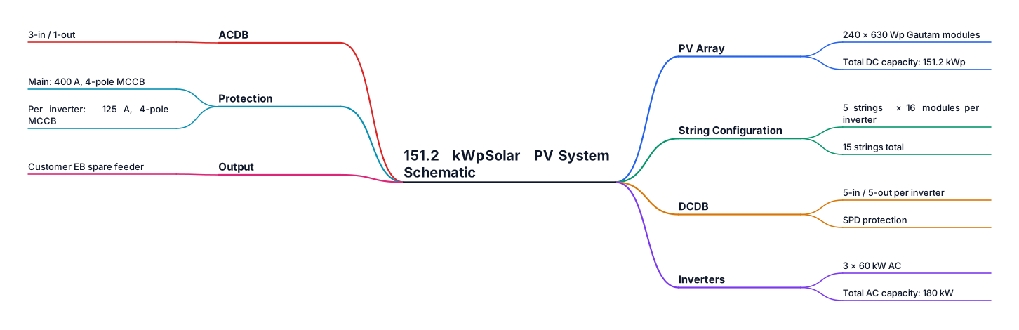
PV capacity: 151.2 kWp DC Inverter capacity: 3 × 60 kW = 180 kW AC - make evvo PV modules: 240 × 630 Wp Gautam String configuration: 5 strings × 16 modules per inverter DCDB: 5-in / 5-out per inverter with spd ACDB: 3-in / 1-out Main protection: 400 A, 4-pole MCCB Inverter protection: 125 A, 4-pole MCCB per inverter Output: Customer EB spare feeder create a scehmeatic drawing
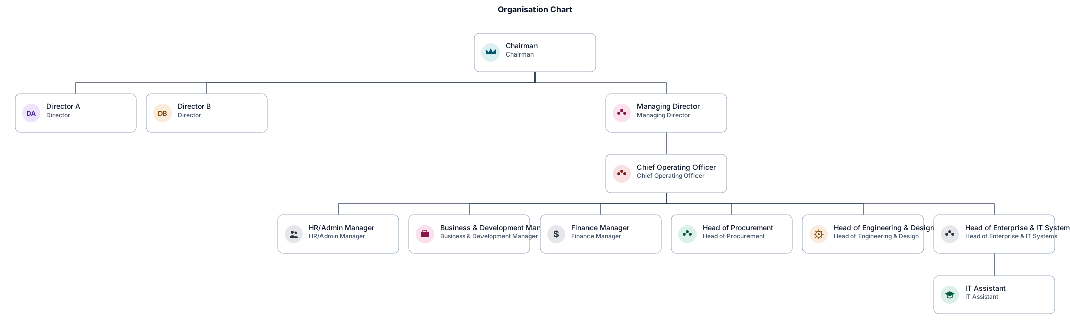
An org chart for an organisation . the chairman , two directors underneath and then a managing director with them then at the next tier under the managing director a chief operating officer . then in the tier under the chief iperating officer we have the hr/ admin managher , Business and developmentr manager , finance manager , head procurement , head of engineering and design and then a head of enterprise and IT systems then under the it sysstems we have an it assistant . its for a tehcnical report so it should be of that standard and be beautiful as well as simple
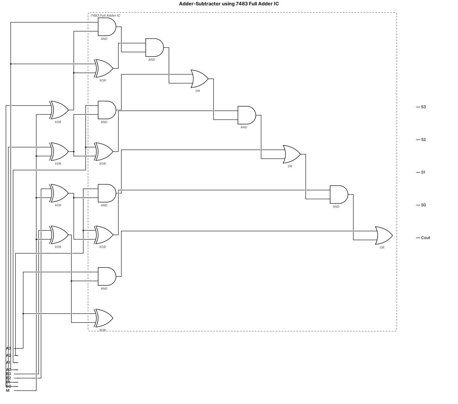
Implement Adder-Subtractor using 7483 Full adder IC
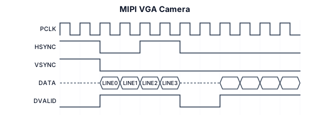
A timing diagram for MIPI VGA camera
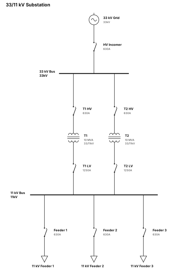
CREATE SLD FOR 33/11 KV SUBSTATION
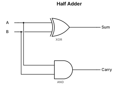
Half adder: Sum = A XOR B, Carry = AB
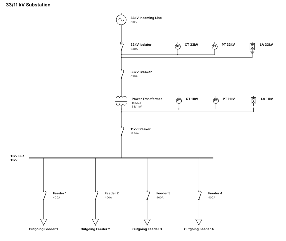
SLD FOR 33/11 KV SUBSTATION
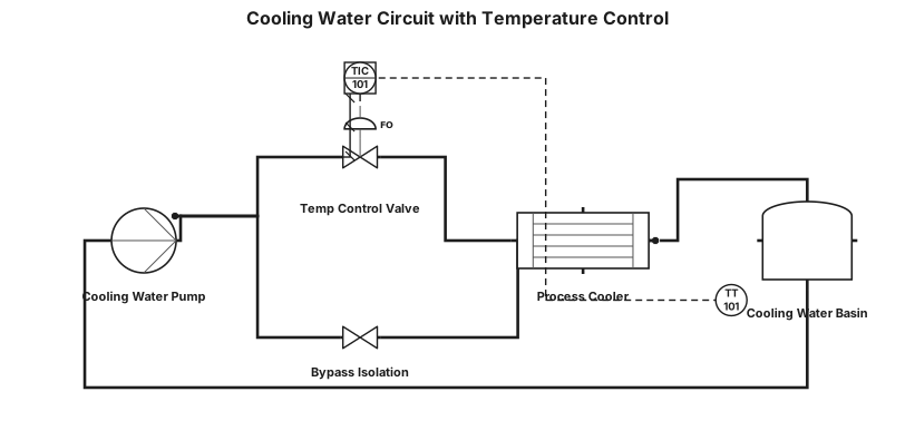
Cooling water circuit with temperature control valve and bypass
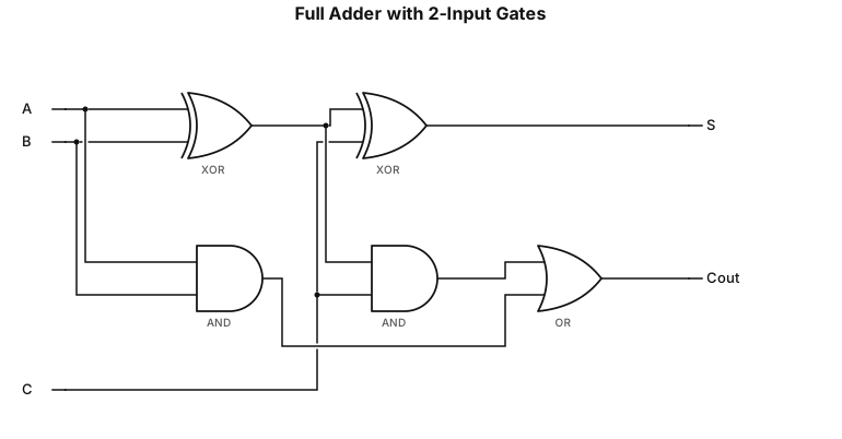
Cout=(A⊕B)C+AB using 2 input gates and S=A⊕B⊕C in one image
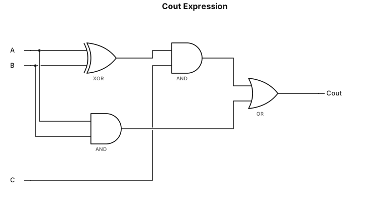
Cout=(A⊕B)C+AB using 2 input gates
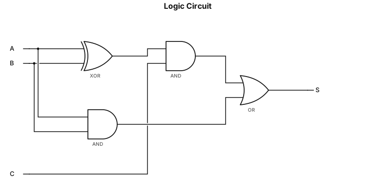
S=(A⊕B)C+AB using 2 input gates