
Create a clean and professional academic 0-Level Data Flow Diagram (DFD) for a college project titled: “ClickMe – AI Event Photo Retrieval System” Use standard DFD notation. IMPORTANT: This is a 0-Level DFD, so show the complete ClickMe application as ONE single central process. Do NOT show internal processes such as face detection, face embedding generation, similarity search, ChromaDB, OpenCV, InsightFace, Docker, or any other internal component. Include exactly TWO external entities: 1. PHOTOGRAPHER 2. GUEST Include exactly ONE central process: “ClickMe – AI Event Photo Retrieval System” Data flows: 1. PHOTOGRAPHER → ClickMe System Label the arrow: “Event Photos + Event ID” 2. GUEST → ClickMe System Label the arrow: “Selfie + Event ID” 3. ClickMe System → GUEST Label the arrow: “Matching Photographs” The diagram should clearly show that the photographer provides event photographs and Event ID to the system, while the guest provides a selfie and Event ID to search for photographs. The system returns matching photographs to the guest. Use: - Standard DFD symbols - External entities as rectangles - The complete ClickMe system as one process - Clearly labelled directional arrows - Black and white academic style - White background - Clean rectangular shapes - Simple professional typography - Landscape orientation - No decorative graphics - No icons - No photographs - No unnecessary text - No extra entities - No extra processes Make the diagram suitable for direct insertion into a college project report. Title/caption should be: “Figure 5.3.1: 0-Level DFD of ClickMe”
Diagram Examples from Real Visitor Prompts
Browse eligible diagrams shared by FreeDiagram visitors, inspect the exact prompts, and build your own version.
Browse 1024 real creationsAll visitor creations
Showing 697–720 of 1024. No stock examples or system defaults. Choose a tool, study a real result, then reopen its prompt as your starting point.
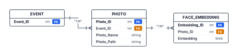
Create a clean academic ER diagram for my AI Event Photo Retrieval System called ClickMe. The system stores event photographs and facial embeddings for selfie-based photo retrieval. Use three main database entities: EVENT, PHOTO, and FACE_EMBEDDING. EVENT contains PK Event_ID. PHOTO contains PK Photo_ID, FK Event_ID, Photo_Name, and Photo_Path. FACE_EMBEDDING contains PK Embedding_ID, FK Photo_ID, and facial Embedding. Show a one-to-many relationship between EVENT and PHOTO because one event contains many photographs. Show a one-to-many relationship between PHOTO and FACE_EMBEDDING because one photograph may contain multiple detected faces and therefore multiple facial embeddings. Show a separate Guest Selfie input outside the database entities. The Guest Selfie is processed to generate a facial embedding and is used for similarity search against the stored facial embeddings in ChromaDB; it is not a permanent database entity. Mention ChromaDB as the vector database used to store and search facial embeddings, but do not represent ChromaDB as an entity. Use standard ERD notation, clear rectangles, PK/FK labels, cardinality 1:M, black-and-white academic style, white background, landscape layout, no unnecessary decoration, suitable for a college project report.
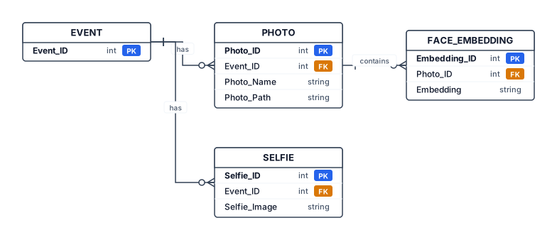
Create a clean academic Entity Relationship Diagram (ERD) for an AI Event Photo Retrieval System called ClickMe. Include four entities: EVENT, PHOTO, FACE_EMBEDDING, and SELFIE. EVENT has Event_ID as the primary key. PHOTO has Photo_ID as the primary key, Event_ID as a foreign key, and Photo_Name/Photo_Path. FACE_EMBEDDING has Embedding_ID as the primary key, Photo_ID as a foreign key, and Embedding. SELFIE has Selfie_ID as the primary key, Event_ID as a foreign key, and Selfie_Image. Show these relationships: one EVENT can have many PHOTOS; one PHOTO can contain multiple FACE_EMBEDDINGS; one EVENT can have multiple SELFIES. Use standard ERD notation, clear rectangles, primary key and foreign key labels, simple black-and-white academic style, no unnecessary decoration, white background, landscape layout, suitable for a college project report.
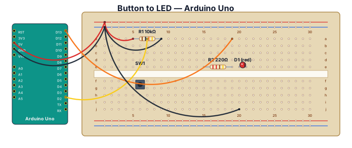
A breadboard wiring diagram for an Arduino UnoQ reading a button press and lighting an LED: button with pull-down resistor on D2, LED with 220-ohm resistor on D13
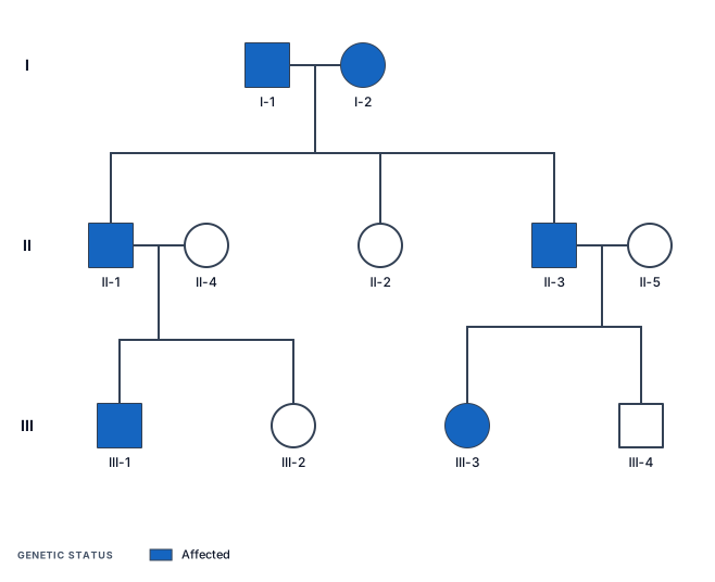
A three‑generation pedigree chart showing autosomal dominant inheritance of widow’s peak, with two affected grandparents, one affected child, one unaffected child, and cousins showing a full range of dominant, heterozygous, and unaffected phenotypes.
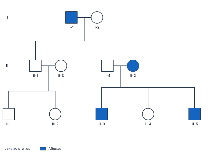
A three‑generation pedigree chart showing autosomal dominant inheritance of widow’s peak, with an affected grandfather, an unaffected grandmother, one unaffected child, one affected child, and grandchildren showing complete absence of the trait in one branch and mixed expression in the other.
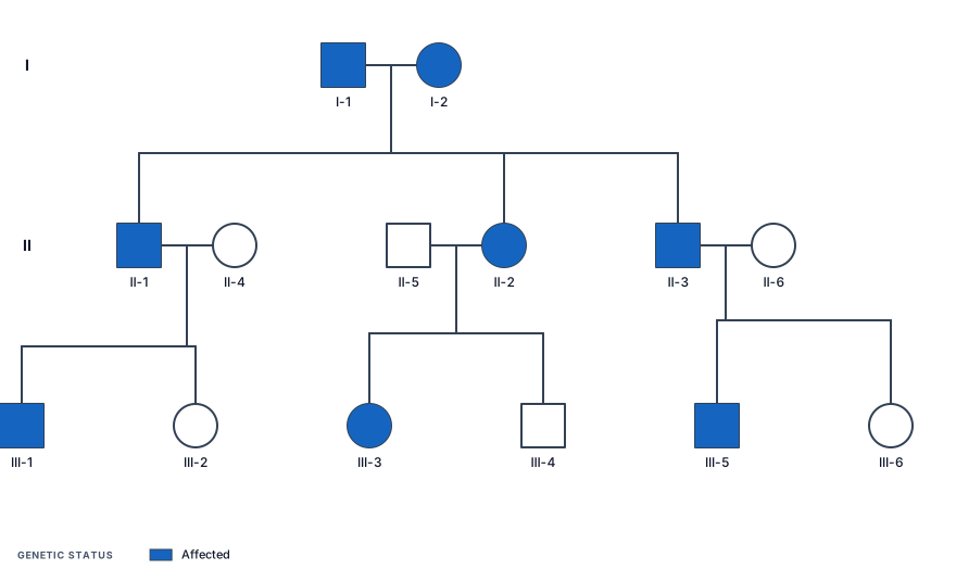
A three‑generation pedigree chart showing autosomal dominant inheritance of widow’s peak, with two affected grandparents, three affected children, and six grandchildren showing both affected and unaffected phenotypes depending on parental genotype
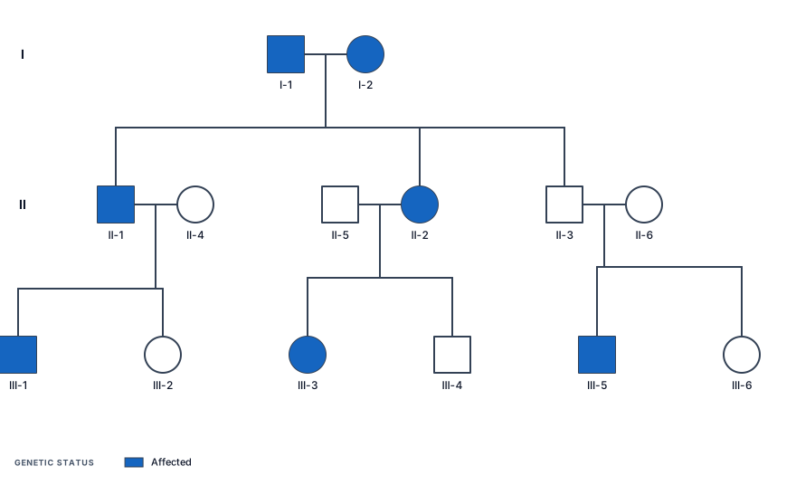
A three‑generation pedigree chart showing autosomal dominant inheritance of widow’s peak, with two affected grandparents, three children with mixed genotypes (one homozygous dominant, one heterozygous, one unaffected), and six grandchildren showing a 1:1 ratio of affected to unaffected individuals across branches. Titled Family C
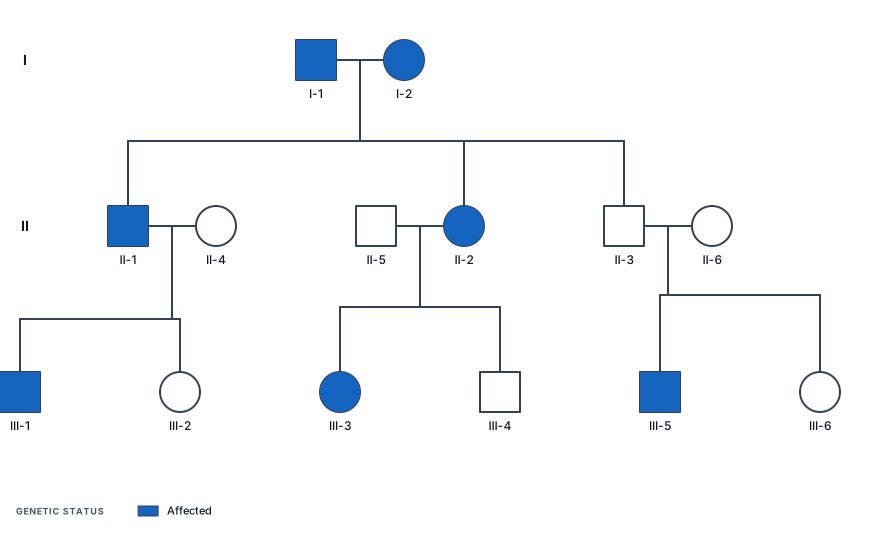
A three‑generation pedigree chart showing autosomal dominant inheritance of widow’s peak, with two affected grandparents, three children with mixed genotypes (one homozygous dominant, one heterozygous, one unaffected), and six grandchildren showing a 1:1 ratio of affected to unaffected individuals across branches
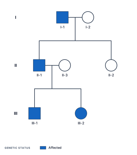
A three‑generation pedigree chart showing autosomal dominant inheritance of widow’s peak, with an affected grandfather, an unaffected grandmother, one affected child, one unaffected child, and two affected grandchildren
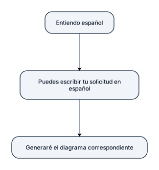
Me entiendes si escribo mi solicitud en español?
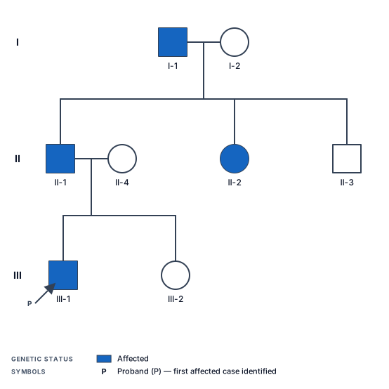
A three-generation pedigree chart showing autosomal dominant inheritance of Huntington disease, with the grandfather affected, two carrier children, and one affected grandchild

5. "What do you know about the proposal process?" You don't need to pretend you're a Shipley expert. Show that you understand the lifecycle. Answer At a high level, I understand the proposal process as starting with understanding the solicitation and identifying every requirement that needs a response. From there, the team builds a compliance matrix, assigns responsibilities, establishes a schedule and coordinates the technical, management and pricing inputs. As the proposal develops, the team goes through reviews and revisions to make sure the response is compliant, accurate and consistent. On the pricing side, you need to develop the underlying cost elements and BOEs, validate the assumptions, build the pricing model and make sure the pricing artifacts align with the technical and contractual requirements. The final stage is really about compliance, quality control and making sure everything is submitted correctly and on time. I haven't owned every part of that lifecycle myself, but I've spent years supporting the pricing portion and working with the teams responsible for it, so I'm very familiar with the environment.

Create a complete, buildable schematic for a MONO 2-band Baxandall audio tone control preamplifier. POWER: - Single +12V DC supply - GND = 0V - Create VREF = +6V using two 10kΩ resistors as a voltage divider. - Add 100µF and 100nF capacitors from VREF to GND. - Use NE5532 dual op-amp. - Show the correct NE5532 pin numbers and power pins. - NE5532 pin 8 = +12V - NE5532 pin 4 = GND AUDIO INPUT: - Mono audio input - Input coupling capacitor = 1µF - Input bias/reference must be connected correctly to VREF. - Add an input volume control using a 50kΩ potentiometer. TONE CONTROL: - Use a proper ACTIVE Baxandall 2-band tone control. - Bass control = 50kΩ potentiometer. - Treble control = 50kΩ potentiometer. - Bass center frequency approximately 100Hz. - Treble center frequency approximately 10kHz. - Tone controls must be centered around VREF for single-supply operation. - Clearly show every resistor and capacitor value. - Clearly show every connection between the tone-control components and the NE5532. OUTPUT: - Mono audio output. - Output must be biased correctly around VREF. - Add an output coupling capacitor so the external amplifier receives no DC. - Output should be suitable for a TPA3116D2 Class-D amplifier input. IMPORTANT: - Use standard electronic schematic symbols. - Show ALL component values. - Show ALL NE5532 pin numbers. - Show +12V, GND and VREF clearly. - Do not omit any component. - Do not use a generic block diagram. - Generate a real electronic schematic with wires and component symbols. - Make it clean, large and easy to read. - The final result must be suitable for manually rebuilding on a PCB.
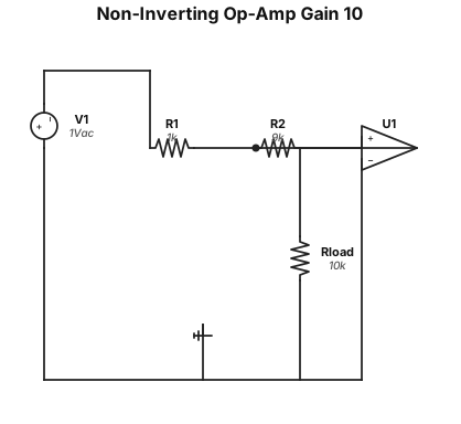
A non-inverting op-amp amplifier circuit with a gain of 10, using a 1 kΩ input resistor and a 9 kΩ feedback resistor
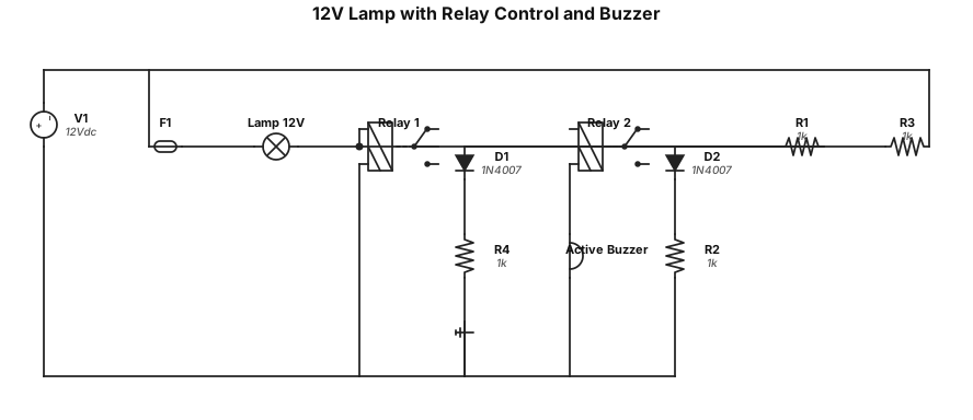
Нарисуй простую электрическую схему: лампа 12 В стоит в силовой цепи вместо предохранителя. Лампа коммутируется нормально разомкнутым контактом реле 1. Катушка реле 1 включена параллельно силовой линии. Второе реле (реле 2) с перекидными контактами управляет активным зуммером: зуммер включён через нормально замкнутый контакт реле 2. Катушка реле 2 питается через NO‑контакт реле 1 (то есть при срабатывании реле 1 реле 2 тоже срабатывает и отключает зуммер). Добавь два защитных диода параллельно катушкам обоих реле. Используй стандартные символы компонентов и подпиши их.»
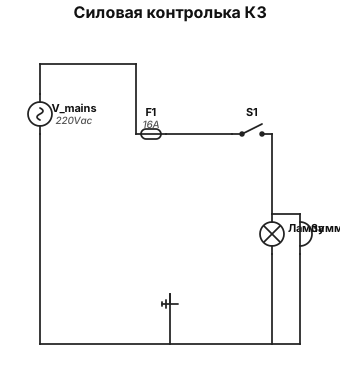
Нужна силовая контролька КЗ есть — лампа горит, зуммер молчит; КЗ нет — лампа не горит (или горит слабо), зуммер пищит.
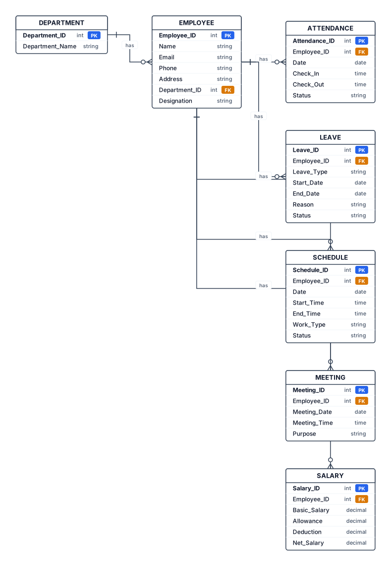
Create a simple, professional black-and-white ER (Entity Relationship) diagram for an Employee Management System college project. Use exactly these 7 entities: 1. EMPLOYEE 2. DEPARTMENT 3. ATTENDANCE 4. LEAVE 5. SCHEDULE 6. MEETING 7. SALARY EMPLOYEE attributes: Employee_ID (PK), Name, Email, Phone, Address, Department_ID (FK), Designation DEPARTMENT attributes: Department_ID (PK), Department_Name ATTENDANCE attributes: Attendance_ID (PK), Employee_ID (FK), Date, Check_In, Check_Out, Status LEAVE attributes: Leave_ID (PK), Employee_ID (FK), Leave_Type, Start_Date, End_Date, Reason, Status SCHEDULE attributes: Schedule_ID (PK), Employee_ID (FK), Date, Start_Time, End_Time, Work_Type, Status MEETING attributes: Meeting_ID (PK), Employee_ID (FK), Meeting_Date, Meeting_Time, Purpose SALARY attributes: Salary_ID (PK), Employee_ID (FK), Basic_Salary, Allowance, Deduction, Net_Salary Relationships: DEPARTMENT has many EMPLOYEES (1:M). EMPLOYEE has many ATTENDANCE records (1:M). EMPLOYEE can have many LEAVE records (1:M). EMPLOYEE can have many SCHEDULE records (1:M). EMPLOYEE can attend many MEETINGS (1:M). EMPLOYEE can have many SALARY records (1:M). Use standard ER diagram notation: - Rectangles for entities - Ovals for attributes - Diamonds for relationships - Clearly mark primary keys (PK) and foreign keys (FK) - Show cardinalities 1:M - Use clean straight connecting lines - Keep EMPLOYEE as the central entity - Arrange the diagram neatly with no overlapping lines - White background, black text and borders - Make all labels large, clear and readable - Suitable for a BCA college project documentation DO NOT include Dashboard, Task, Task Scheduler, or Training. Do not add any extra entities or attributes.
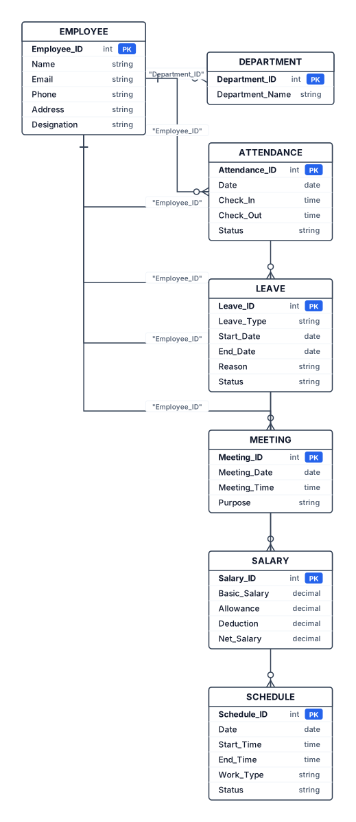
Entities & important attributes EMPLOYEE Employee_ID (PK) Name Email Phone Address Department_ID (FK) Designation DEPARTMENT Department_ID (PK) Department_Name ATTENDANCE Attendance_ID (PK) Employee_ID (FK) Date Check_In Check_Out Status LEAVE Leave_ID (PK) Employee_ID (FK) Leave_Type Start_Date End_Date Reason Status MEETING Meeting_ID (PK) Employee_ID (FK) Meeting_Date Meeting_Time Purpose SALARY Salary_ID (PK) Employee_ID (FK) Basic_Salary Allowance Deduction Net_Salary SCHEDULE Schedule_ID (PK) Employee_ID (FK) Date Start_Time End_Time Work_Type Status
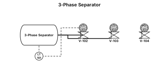
3-phase separator
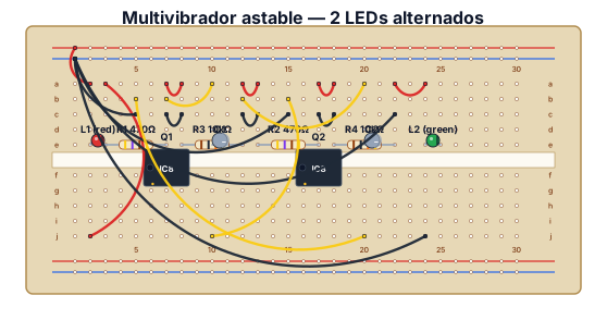
En este circuito se iluminará alternativamente L1 o L2. Los dos transistores trabajan en conmutación es decir cuando uno conduce (saturación) el otro no (corte) y viceversa. Al conectar la alimentación supongamos que L1 se enciende y L2 está apagado, no obstante por L2 circula una muy pequeña corriente (insuficiente para encenderlo) que pasa por R4 atraviesa C2 y llega a la base de Q1, por lo que L1 sigue encendido y C2 cargándose. Cuando C2 esta cargado impide el paso de la corriente, bloquea Q1 y L1 se apaga. Ahora circula una muy pequeña corriente a través de L1 (insuficiente para encenderlo) y R1 hasta la base de Q2 por lo que éste conduce, se enciende L2 y comienza a cargarse C1. Mientras C1 se carga C2 se descarga a través de R3. Después el proceso se repite
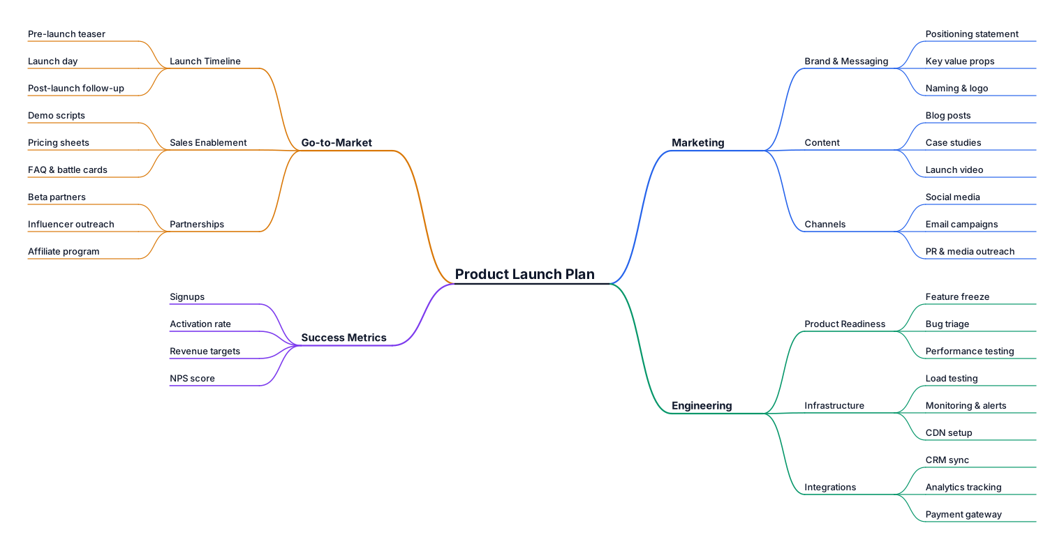
A mind map for planning a product launch, covering marketing, engineering, and go-to-market
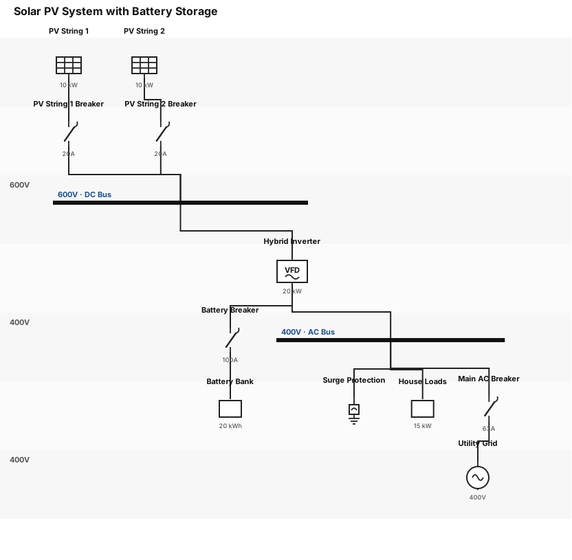
Solar PV system, with 2 strings of panels connected to an Inverter. Battery system and protection equipments.

tolong generate charg organization based in ni : EHS DEPARTMENT Operation Manager Syammizam bin Abu Bakar ↓ EHS Manager Patriscia Kaching Anak Padong ↓ Assistant Manager Mohd Afiq bin Nizam ↓ EHS Coordinator Rabbiatul Addawiah binti Sutari ↓ Reporting Analyst * Sharanya * Nur Syahirah Kemudian di bawah EHS Coordinator/Reporting Analyst, operasi terbahagi kepada 2 branch: JB Engineer JB * Vacant Senior Technician * Muhammad Amir Ezzat bin Hasan * Shahiran bin Azman Hamid Technician JB * Syaqeer * Ali Hanafi * Haziq Hazmi Kertih Engineer Kertih * Amar Ridhwan bin Johar Technician Kertih * Muhammad Redha * Mohd Basyir
Focused examples and prompt ideas
Start with the complete visitor wall above, then use these focused collections when you want a narrower subject and more prompt context.
The first curated collection is being prepared.