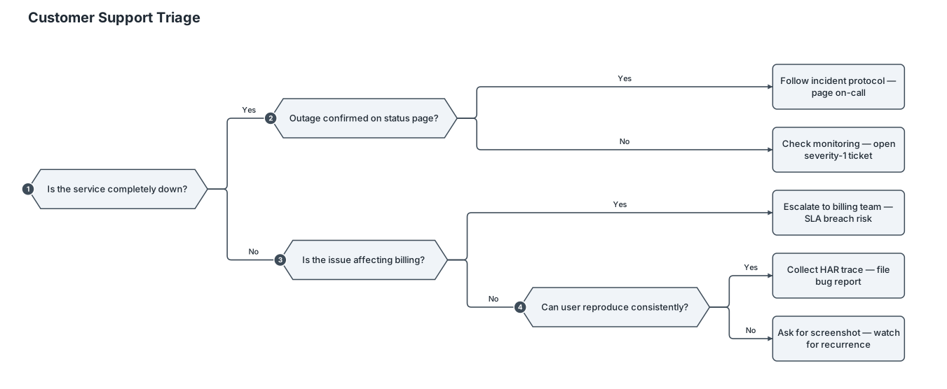
Example of decision tree left to right with terminal nodes.
NODE ARCHIVE · REAL DIAGRAM BRIEFS
Diagram Examples from Real Visitor Prompts
Browse eligible diagrams shared by FreeDiagram visitors, inspect the exact prompts, and build your own version.
Browse 3286 real creationsCOMMUNITY OUTPUTS · EXACT PROMPTS
All visitor creations
Showing 1273–1296 of 3286. No stock examples or system defaults. Choose a tool, study a real result, then reopen its prompt as your starting point.
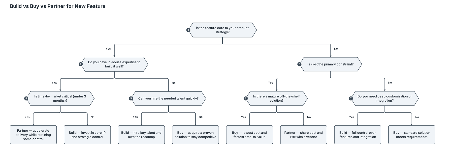
A decision tree for whether a startup should build, buy, or partner for a new feature, evaluating cost, speed, and strategic control
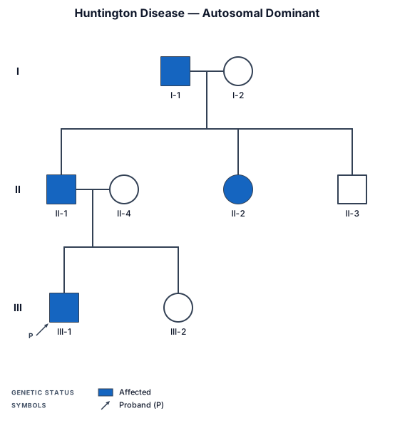
A three-generation pedigree chart showing autosomal dominant inheritance of Huntington disease, with the grandfather affected, two carrier children, and one affected grandchild
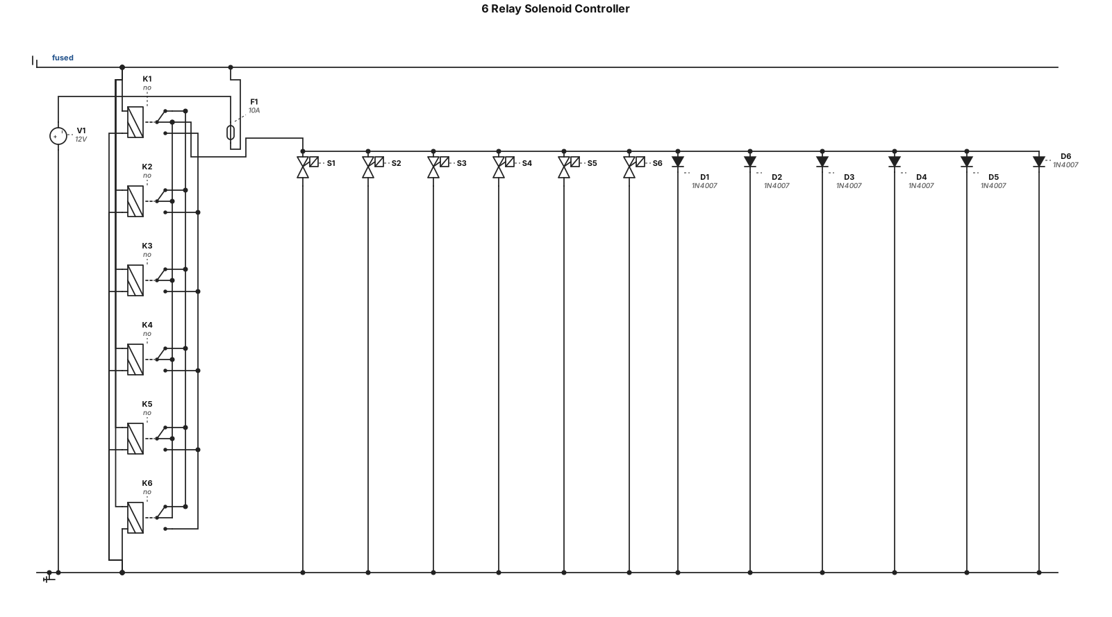
6 12v relays controlling solenoids
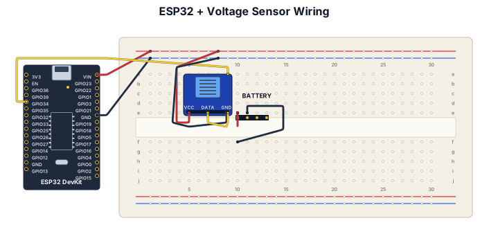
use esp32 and voltage sensor,give connections to read the voltage data
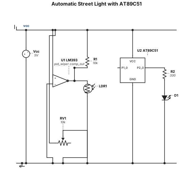
“Create an Automatic Street Light circuit using AT89C51 8051, LDR, 10k resistor, LM393 comparator, 10k potentiometer, LED and 330 ohm resistor. LDR voltage divider output goes to LM393 positive input. Potentiometer wiper goes to negative input. LM393 output goes to P1.0. P2.0 drives LED through 330 ohm resistor. Show +5V and GND connections and clearly label every pin.”
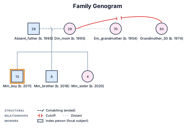
MM 13 year old boy, MM brother 6 year old, MM sister 4 year old DM Mom 29 year old, Absent father 29 years old, grandmother 50 years old not connected to daughter, EM grandmother 70 year old .
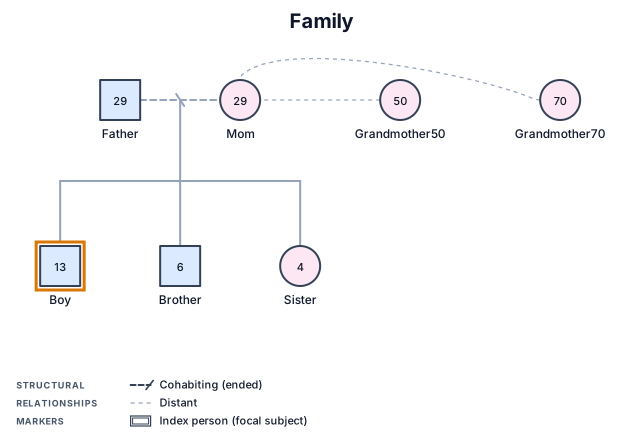
13 year old boy, brother 6 year old, sister 4 year old Mom 29 year old, Absent father 29 years old, grandmother 50 years old not connected to daughter, grandmother 70 year old .
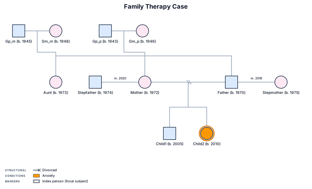
A three-generation genogram for a family therapy case: grandparents on both sides, parents who divorced and remarried, two children — the younger showing anxiety
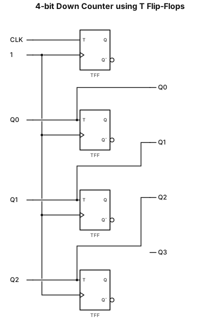
Design and set up a 4-bit down counter using T-flip flop
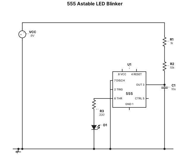
astable multivibrator 555 timer led blinking
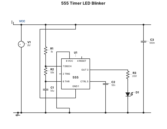
astable multivibraator 555 timer lrd blinking
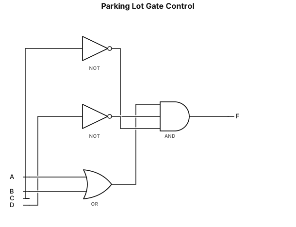
I want to design a digital logic circuit for a parking lot system. The system has four input switches: * A = Car detected at Entrance 1 * B = Car detected at Entrance 2 * C = Parking lot full * D = Emergency mode The output is: * F = Gate Open The logic should work as follows: The gate should open when a car is detected at either entrance (A OR B), as long as the parking lot is not full (NOT C) and the system is not in emergency mode (NOT D). Boolean expression: F = (A + B) · C’ · D’ Please create the complete logic gate diagram using only AND, OR, and NOT gates. I also need a detailed explanation of every connection. Clearly identify: 1. Each input. 2. Each AND, OR, and NOT gate. 3. Which input goes to which gate input. 4. Which gate output connects to which gate input. 5. The final output F. Explain the connections step by step so I can build the same circuit physically or in a digital logic simulator.
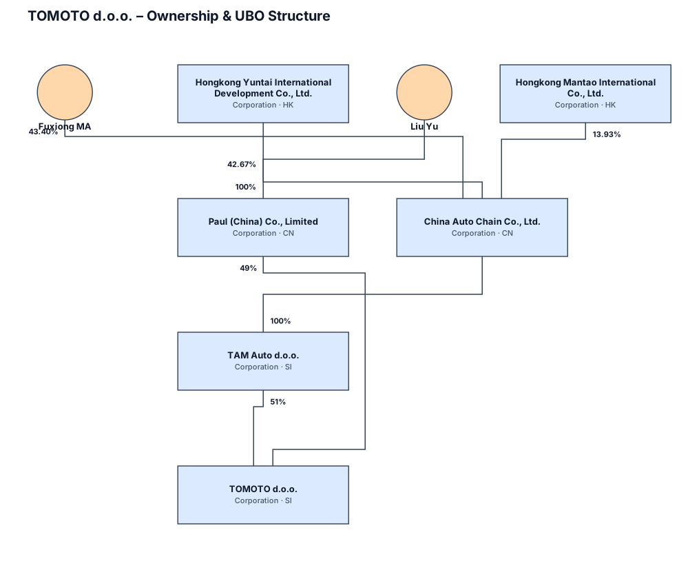
Create a professional corporate ownership and UBO structure chart for bank KYC purposes. Title: TOMOTO d.o.o. – Ownership & UBO Structure Structure: TOMOTO d.o.o. (Slovenia) - 51% owned by TAM Auto d.o.o. - 49% owned by Paul (China) Co., Limited TAM Auto d.o.o. - 100% owned by China Auto Chain Co., Ltd. China Auto Chain Co., Ltd. - 43.40% owned by Fuxiong MA (Individual) - 42.67% owned by Hongkong Yuntai International Development Co., Ltd. (Corporation) - 13.93% owned by Hongkong Mantao International Co., Ltd. (Corporation) Paul (China) Co., Limited - 100% owned by Liu Yu (Individual) Show all ownership percentages clearly on the connecting lines. Design requirements: - Very clean and professional bank/KYC style - White background - Dark navy blue corporate boxes - Individual persons shown with a slightly different but professional box style - Thin straight connecting lines - Ownership percentages displayed clearly next to the lines - No icons - No illustrations - No gradients - No decorative elements - No unnecessary text - Compact horizontal layout - Keep all company names fully visible - Make the ultimate natural persons clearly identifiable - Suitable for ICBC / bank KYC submission
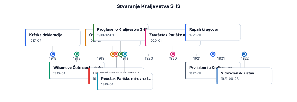
1917 │ ├── Srpanj: Krfska deklaracija │ 1918 │ ├── Početak godine: Wilsonove Četrnaest točaka ├── Početak listopada: Osnovano Narodno vijeće SHS ├── 29. listopada: Hrvatski sabor prekida veze s Austro-Ugarskom └── 1. prosinca: Proglašeno Kraljevstvo SHS │ 1919 │ ├── Siječanj: Početak Pariške mirovne konferencije │ 1920 │ ├── Siječanj: Završetak Pariške mirovne konferencije ├── Studeni: Prvi izbori u Kraljevstvu SHS └── Studeni: Rapalski ugovor │ 1921 │ └── 28. lipnja: Vidovdanski ustav
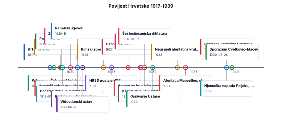
1917 │ ├── Srpanj: Krfska deklaracija │ 1918 │ ├── Početak godine: Wilsonove Četrnaest točaka ├── Početak listopada: Osnovano Narodno vijeće SHS ├── 29. listopada: Hrvatski sabor prekida veze s Austro-Ugarskom └── 1. prosinca: Proglašeno Kraljevstvo SHS │ 1919 │ ├── Siječanj: Početak Pariške mirovne konferencije │ 1920 │ ├── Siječanj: Završetak Pariške mirovne konferencije ├── Studeni: Prvi izbori u Kraljevstvu SHS └── Studeni: Rapalski ugovor │ 1921 │ └── 28. lipnja: Vidovdanski ustav │ 1924 │ └── Rimski sporazum, Rijeka pripada Italiji │ 1925 │ └── HRSS postaje HSS │ 1927 │ └── Osnivanje Seljačko-demokratske koalicije (SDK) │ 1928 │ ├── 20. lipnja: Atentat na hrvatske zastupnike └── Kolovoz: Smrt Stjepana Radića │ 1929 │ ├── 6. siječnja: Šestosiječanjska diktatura └── Kraljevstvo SHS postaje Kraljevina Jugoslavija │ 1930 │ └── Osnivanje Ustaše │ 1933 │ └── Neuspjeli atentat na kralja Aleksandra u Zagrebu │ 1934 │ └── Atentat u Marseilleu, ubijen kralj Aleksandar │ 1939 │ ├── 26. kolovoza: Sporazum Cvetković-Maček ├── Stvorena Banovina Hrvatska └── Njemačka napada Poljsku, počinje Drugi svjetski rat ``
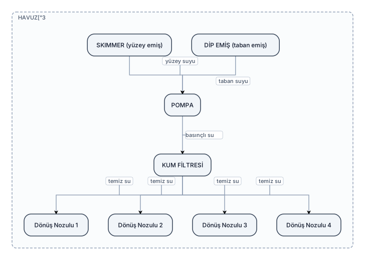
3 × 8 metre, yaklaşık 1,50 metre derinliğinde taşmasız bir yüzme havuzu için ANİMASYON / HAREKETLİ ŞEMA hazırla. Ben teknik konuları zor anlıyorum. Bu nedenle amaç teknik proje çizmek değil, SUYUN NASIL DOLAŞTIĞINI GÖRSEL OLARAK ANLATMAK. Sistemde: - 1 adet SKIMMER - 1 adet DİP EMİŞ - 1 adet POMPA - 1 adet KUM FİLTRESİ - 4 adet DÖNÜŞ NOZULU olsun. ANİMASYONDA SUYUN HAREKETİNİ GÖSTER: 1. Havuzdaki suyun bir kısmı SKIMMER'den emilsin. 2. Havuz tabanındaki su DİP EMİŞTEN emilsin. 3. SKIMMER
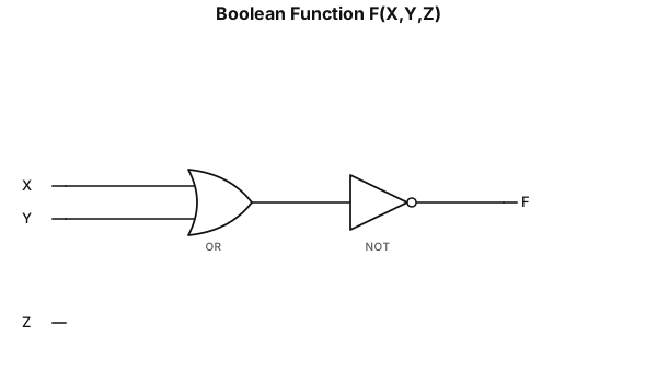
F(X,Y,Z)=(X+Y)’
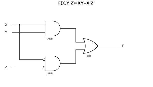
F(X,Y,Z)=XY+X’Z’
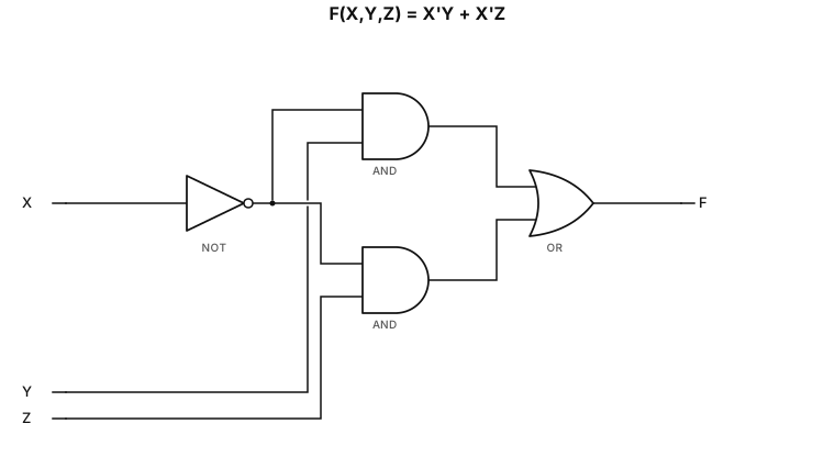
F(X,Y,Z)=X’Y+X’Z
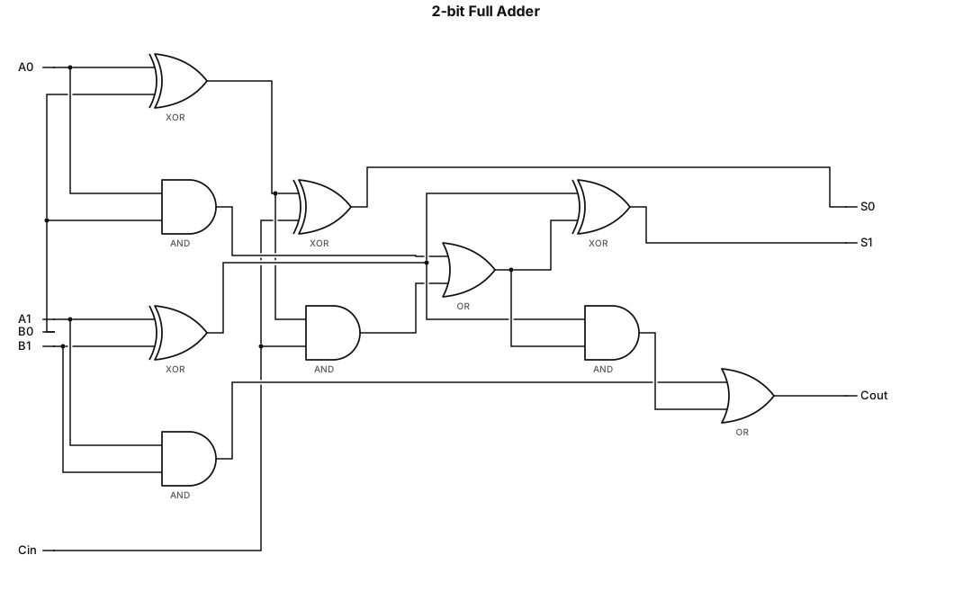
A logic gate circuit for a 2-bit full adder using AND, OR, and XOR gates with inputs A, B, and carry-in, and outputs sum and carry-out
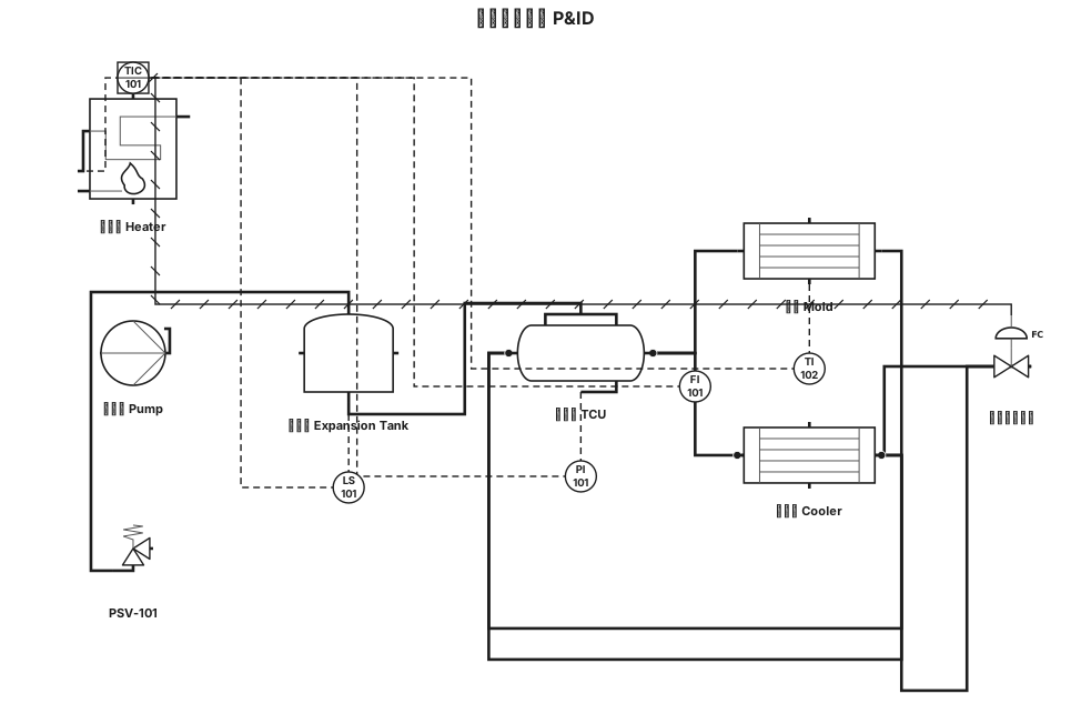
模具用模溫機 p&id
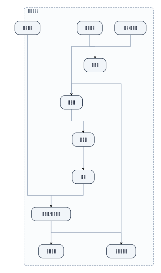
模具用模溫機流程
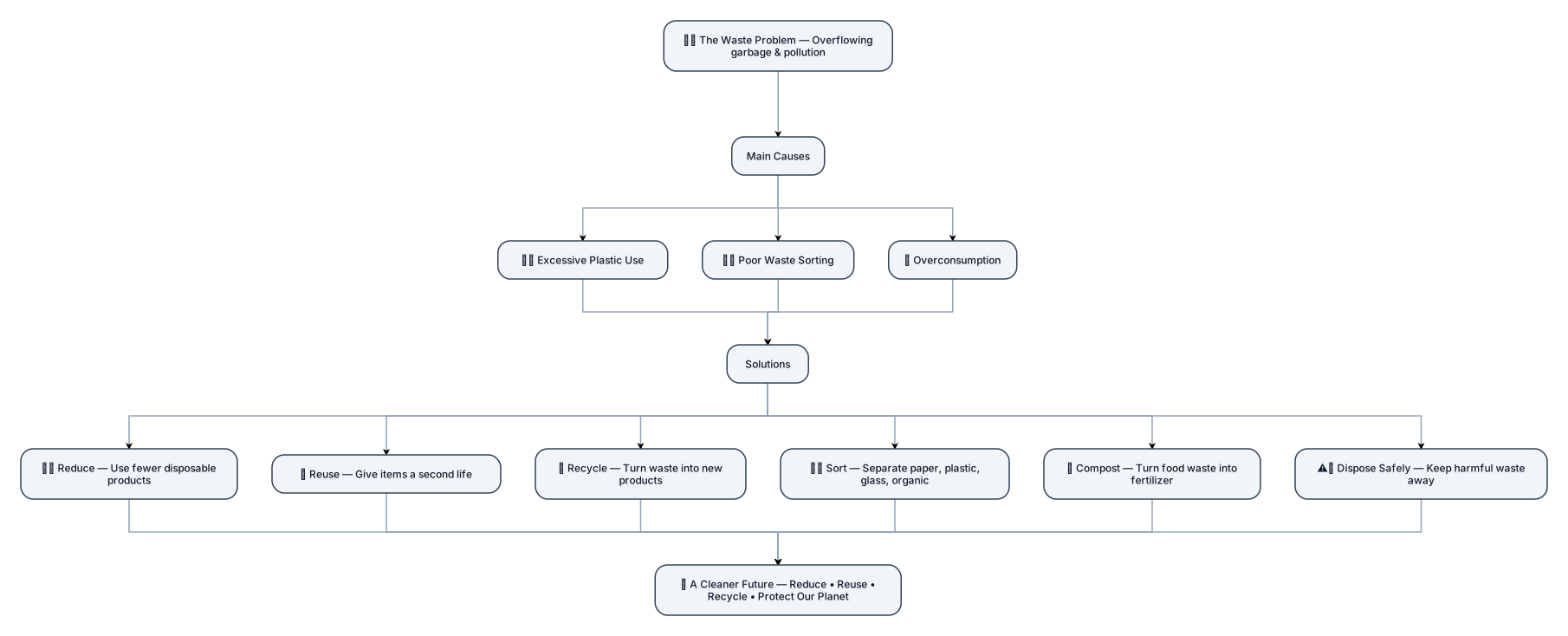
Design a professional, clean, and visually attractive educational infographic titled "Waste Management: Problems & Solutions". Use a clear vertical flowchart layout with a logical structure from top to bottom. 1. Main Problem: Put a large central section at the top titled "The Waste Problem", with a simple illustration of overflowing garbage and pollution. 2. Causes: Under it, create a section titled "Main Causes" with 3 organized cards: • Excessive Plastic Use • Poor Waste Sorting • Overconsumption 3. Solutions: Below the causes, create a large section titled "Solutions" with 6 equal-sized cards arranged neatly in a 2×3 grid: • Reduce — Use fewer disposable products. • Reuse — Give items a second life. • Recycle — Turn waste into new products. • Sort — Separate paper, plastic, glass, and organic waste. • Compost — Turn food waste into natural fertilizer. • Dispose Safely — Keep harmful waste away from the environment. 4. Final Result: At the bottom, add a highlighted green section titled "A Cleaner Future" with the message "Reduce • Reuse • Recycle • Protect Our Planet". Design requirements: Use a professional green, blue, and white color palette. Use consistent icons, clean typography, equal spacing, aligned elements, rounded cards, and clear visual hierarchy. Make the design look like a high-quality school science project. Avoid clutter, excessive text, random decorations, and overlapping elements. Make every section clearly separated and easy to understand at a glance. Use arrows to show the flow from Problem → Causes → Solutions → Cleaner Future. Do not make it look like a presentation slide; make it look like a polished infographic poster.